ECEU530 Schedule ECE U530 Classes on November 6 and 8 will be in - - PDF document

eceu530
SMART_READER_LITE
LIVE PREVIEW

ECEU530 Schedule ECE U530 Classes on November 6 and 8 will be in - - PDF document

ECEU530 Schedule ECE U530 Classes on November 6 and 8 will be in 429 Dana Digital Hardware Synthesis Homework 5 due Wednesday, November 8 Write the Datapath for the calculator from ECEU323 in VHDL Prof. Miriam Leeser Use the


slide-1
SLIDE 1

ECEU530

ECE U530 Digital Hardware Synthesis

  • Classes November 6 and 8 are in 429 Dana!
  • Lecture 15:
  • Homework 5: Datapath
  • How to write a testbench for synchronous circuits
  • HW 5: Due Wednesday, November 8
  • Project Progress reports due

Friday, November 10

ECE U530 F06

lect15.ppt

  • Prof. Miriam Leeser

mel@coe.neu.edu November 6, 2006

ECE U530 F’06 2

lect15.ppt

Schedule

  • Classes on November 6 and 8 will be in 429 Dana
  • Homework 5 due Wednesday, November 8
  • Write the Datapath for the calculator from ECEU323 in VHDL
  • Use the posted entity
  • Project progress report due Friday, November 10:
  • and email to me telling me where your project stands
  • some working VHDL code in your home directory
  • Homework 6: Lab 5 due Wednesday November 15
  • November 15th and 20th: student presentations on

projects: sign up for a date to do your project presentation

  • Sign up to demo your working project code

November 20th or 21st

ECE U530 F’06 3

lect15.ppt

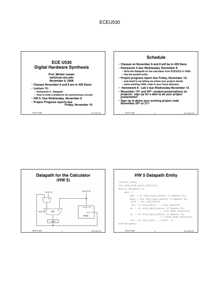
Datapath for the Calculator (HW 5)

ECE U530 F’06 4

lect15.ppt

HW 5 Datapath Entity

library ieee; use ieee.std_logic_1164.all; entity datapath is port ( din : in std_logic_vector (3 downto 0); dout : out std_logic_vector (3 downto 0); cout : out std_logic; sm : in std_logic; -- mux selector sa : in std_logic_vector (2 downto 0);

  • - alu mode selectors

ss : in std_logic_vector (1 downto 0);

  • - stack mode selectors

clk : in std_logic -- clock ); end datapath;

slide-2
SLIDE 2

ECEU530

ECE U530 F’06 5

lect15.ppt

Stack for Datapath

entity stack is port( clk, reset : in std_logic; -- clock ss : in std_logic_vector (1 downto 0); din : in std_logic_vector (4 downto 0); tos : out std_logic_vector (4 downto 0) ); end stack; architecture behavioral of stack is begin

  • - <<enter your statements here>>

end behavioral;

ECE U530 F’06 6

lect15.ppt

Implement the Stack:

Stack Function Stack select hold 0, 1 push 2 pop 3

  • In lab, used shift registers to implement the stack
  • In VHDL, use behavioral code to implement the stack
  • How ?
  • Hint: Create internal state for the “stack”
  • Looks like a simple state machine
  • Output is simply TOS
  • Note: Stack has an asynchronous reset

ECE U530 F’06 7

lect15.ppt

Stack

ARCHITECTURE behavioral of stack IS SUBTYPE five_bit is std_logic_vector (4 downto 0); TYPE four_array IS ARRAY (3 downto 0) OF five_bit; SIGNAL stk, next_stack : four_array; begin

  • - process for updating stack state
  • Why do you need a new stack?

ECE U530 F’06 8

lect15.ppt

Shift Register

entity shift is port(Clk, SI : in std_logic; SO : out std_logic); end shift; architecture archi of shift is signal next_state, state: std_logic_vector(3 downto 0); begin process begin next_state <= state(2 downto 0) & SI; wait until (Clk'event and Clk = '1'); state <= next_state; end process; SO <= state(3); end archi;

slide-3
SLIDE 3

ECEU530

ECE U530 F’06 9

lect15.ppt

Testbench Design

  • Already seen basics of how to write one

(Lecture 7)

  • Libraries, Entity, Architecture
  • Instance of Unit Under Test (UUT)
  • Process to control clock
  • Today: More important concepts
  • Which input combinations should I try?
  • Self-checking testbenches

ECE U530 F’06 10

lect15.ppt

Simple UUTs

  • Combinational circuits are easy to test
  • Inputs can come in any order
  • Outputs are only dependent on current input, not previous

inputs

  • Usually we can test combinational circuits

exhaustively (all possible combinations of inputs)

  • loops are often useful here

ECE U530 F’06 11

lect15.ppt

Simple UUT: AOI

  • ! " #$

$%

  • &&'
  • ()!%"#%%

&'

ECE U530 F’06 12

lect15.ppt

Simple UUT: Testbench (1)

  • &** ''
  • &

+ $ $% +

slide-4
SLIDE 4

ECEU530

ECE U530 F’06 13

lect15.ppt

Simple UUT: Testbench (2)

$', -% $

  • $ +).,% )./%

).% ).-% ).% &$ '$$)-

() '' % /-

  • &

ECE U530 F’06 14

lect15.ppt

What does it do?

  • cycles through 0(0000) to 15(1111)

are assigned to bits of

  • This covers all possible inputs to the circuit
  • Coverage is an important term when testing any

circuit

  • “How much functionality did I actually test?”

ECE U530 F’06 15

lect15.ppt

How do I know it works? (1)

  • Inspection: Run it in Modelsim and see if the output is

what you expect

  • Have to figure out all the correct outputs yourself
  • There are only 4 inputs (16 possible values) here, so this is

pretty easy and doable

  • What if I have a lot of inputs, or a more complex circuit?

ECE U530 F’06 16

lect15.ppt

How do I know it works? (2)

  • Golden Standard: Compare the output to another

circuit which implements the same function

  • Ex.: Behavioral model vs. Structural model
  • Instantiate a “standard” circuit alongside the UUT,

connected to the same inputs

  • If the outputs are the same, the UUT works
  • Requires a circuit that already works!
slide-5
SLIDE 5

ECEU530

ECE U530 F’06 17

lect15.ppt

Golden Standard example

  • $& +

).,% )./% ).% ).-% ).% $ + ).,% )./% ).% ).-% ).% $ %

ECE U530 F’06 18

lect15.ppt

How do I know it works? (3)

  • Self-checking: Write the correct answers directly into

the testbench

  • VHDL has an
  • function for just this sort of concept

(textbook p.77)

  • You still need to know what the outputs are supposed to be
  • No more squinting at Modelsim waveforms!

ECE U530 F’06 19

lect15.ppt

Assert: Syntax

  • 1

1 1 1% % % % 2 2 2 23 3 3 3+ + + +4 4 4 4 5 5 5 5 2' 2' 2' 2'' ' ' ' 5 5 5 5 ' ' ' ' )67 )67 )67 )67

  • The error message is printed if the assertion fails, i.e.

the condition is not met

  • In other words, 1

1 1 1 should be the CORRECT

value

ECE U530 F’06 20

lect15.ppt

Assert: Parameters

  • There is a default error message (“Assertion

violation”) if you don’t include one

  • '

' ' ' defaults to

  • Setting '

' ' ' to

  • will cause your simulation to

stop if the assertion fails

  • This is configurable inside the simulator
slide-6
SLIDE 6

ECEU530

ECE U530 F’06 21

lect15.ppt

Assert: Example

$ +).,% )./% ).% ).-% ).% &$ '$$)-

() '' % / ),%/%% %-%%%% 384 ' 9

  • ECE U530 F’06

22

lect15.ppt

Complex Circuits

  • What makes a circuit harder to test?
  • Memory devices (stack, registers, RAM, FSMs)
  • Large numbers of inputs
  • We can’t just specify all combinations anymore
  • “A, then B” is now different from “B, then A”
  • Our simulation would take days!
  • We have to pick and choose our test vectors so that we

cover as much functionality as possible

ECE U530 F’06 23

lect15.ppt

What is a Test Vector ?

  • A collection of inputs (possibly extending across

multiple clock cycles) and the expected corresponding outputs

  • When you apply the inputs, you should get the
  • utputs
  • You can write your testbenches as a collection of test

vectors, complete with output checking

ECE U530 F’06 24

lect15.ppt

Designing Test Vectors (1)

  • Questions to ask yourself:
  • What functions can my circuit perform?
  • Along what paths can the data flow?
  • Which inputs are data, and which are control?
slide-7
SLIDE 7

ECEU530

ECE U530 F’06 25

lect15.ppt

Designing Test Vectors (2)

  • What functions can my circuit perform?
  • An ALU can Add, Subtract, AND, XOR, etc.
  • A stack can Push, Pop, and Hold
  • If there’s only one function, you probably have a “simple”

circuit

  • Different levels of abstraction lead to different answers: a

datapath can Push, And(TOS,Inp), And(TOS,TOS2), etc…

ECE U530 F’06 26

lect15.ppt

Designing Test Vectors (3)

  • Along what paths can the data flow?

ECE U530 F’06 27

lect15.ppt

Designing Test Vectors (4)

  • Which inputs are control?
  • It’s most important to test all possible control combinations –

if one of these doesn’t work, part of your circuit is unusable

  • Which inputs are data?
  • For now, you only need to worry about each data path – not

all possible data words

  • Pick input words that are convenient (5+A=F)

ECE U530 F’06 28

lect15.ppt

Testbench = A Set of Vectors

  • A good series of test vectors gives you confidence

that the entire circuit works

  • Not every vector needs to test every gate
  • Coverage is a way of talking about which gates (or

functions) are tested by which test vectors

  • The union of the coverage of all your test vectors

should be your entire circuit

slide-8
SLIDE 8

ECEU530

ECE U530 F’06 29

lect15.ppt

Test Vector Example

** :-1 +();-<()3--4 ()3--4()3-4 /- ()3----4()3-4 /- )3--4%

What have we covered?

A PassA Hold Push

ECE U530 F’06 30

lect15.ppt

Coverage Chart (1)

√ √ √ √ √ √ √ √ √ √ √ √ √ √ √ √ 1 XOR Add PassB PassA Hold Pop Push B A # ALU Stack Mux

  • Goal: Every column should have at least
  • ne check mark once all the test vectors are

designed

ECE U530 F’06 31

lect15.ppt

Coverage Chart (2)

Stack- ALU Reg- Mux √ √ √ √ √ √ √ √ √ √ √ √ √ √ √ √ √ √ √ √ 1 Stack- Output Reg- Stack ALU- Reg Mux- ALU Input- Mux

  • Don’t forget to count coverage on your

datapaths also

ECE U530 F’06 32

lect15.ppt

Implementation Details

  • It’s good to write testbenches as a series of test

vectors

  • Use comments (and whitespace) to delineate each test vector
  • Use a single process with
  • statements between

vectors

  • Run your infrastructure signals (like clk) in a second process
slide-9
SLIDE 9

ECEU530

ECE U530 F’06 33

lect15.ppt

Summary

  • Simple circuits can be exhaustively tested using
  • loops
  • Simple circuits have only one or two functions and no

memories or sequential elements

  • Self-checking test vectors make debugging your

circuit much easier

  • The
  • statement makes it easy

ECE U530 F’06 34

lect15.ppt

Summary

  • Think about complex circuits in terms of the

functions they provide

  • Make sure you test every function at least once
  • Don’t forget to cover every datapath, too
  • Good testbenches:
  • Have 100% coverage
  • Are easy for a human to follow
  • Check themselves

ECE U530 F’06 35

lect15.ppt

Handshaking

  • En -- an input signal telling the hardware to start
  • Valid -- an output signal saying the result is ready
  • What is wrong with this model?

Sender Hardware En inputs Valid result

ECE U530 F’06 36

lect15.ppt

Handshaking

  • One signal for input: Enable
  • One signal for output: Valid
  • How do you know if HW is ready ?
  • How do you know that HW has read the input data?
  • How does HW know that Sender has read the output?
slide-10
SLIDE 10

ECEU530

ECE U530 F’06 37

lect15.ppt

Signaling Protocol

Sender Receiver req ack data

  • Signaling Protocol: communication protocol

req: initiate an action ack: signal completion of that action

  • Two handshake signals for send data

ECE U530 F’06 38

lect15.ppt

Control Signaling Protocol

  • Four-phase Handshaking protocol
  • Level signaling or return to zero

Sender Receiver req ack data

ECE U530 F’06 39

lect15.ppt

Control Signaling Protocol

  • Two-phase Handshaking protocol
  • Transition signaling or Non-return to zero

Sender Receiver req ack data

ECE U530 F’06 40

lect15.ppt

Importance of Handshaking

  • Hardware needs to know when inputs are ready
  • Software needs to know when results are valid
  • Different designs can have different timing
  • Behavioral
  • Register Transfer Level (RTL)
  • Pipelined version vs. non-pipelined version
  • Can use the same testbench with different hardware

timing if you use handshaking in your hardware design