ECEU530 Schedule ECE U530 Homework 4 due Wednesday, October 23 - - PDF document

eceu530
SMART_READER_LITE
LIVE PREVIEW

ECEU530 Schedule ECE U530 Homework 4 due Wednesday, October 23 - - PDF document

ECEU530 Schedule ECE U530 Homework 4 due Wednesday, October 23 Digital Hardware Synthesis Write testbench for ALU Use a function Prof. Miriam Leeser Review in class on Monday, October 30 mel@coe.neu.edu I will hand out a


slide-1
SLIDE 1

ECEU530

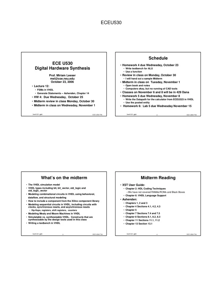
ECE U530 Digital Hardware Synthesis

  • Lecture 12:
  • FSMs in VHDL
  • Generate Statements -- Ashenden, Chapter 14
  • HW 4: Due Wednesday, October 25
  • Midterm review in class Monday, October 30
  • Midterm in class on Wednesday, November 1

ECE U530 F06

lect12.ppt

  • Prof. Miriam Leeser

mel@coe.neu.edu October 23, 2006

ECE U530 F’06 2

lect12.ppt

Schedule

  • Homework 4 due Wednesday, October 23
  • Write testbench for ALU
  • Use a function
  • Review in class on Monday, October 30
  • I will hand out a sample Midterm
  • Midterm in class on Tuesday, November 1
  • Open book and notes
  • Computers okay, but no running of CAD tools
  • Classes on November 6 and 8 will be in 429 Dana
  • Homework 5 due Wednesday, November 8
  • Write the Datapath for the calculator from ECEU323 in VHDL
  • Use the posted entity
  • Homework 6: Lab 5 due Wednesday November 15

ECE U530 F’06 3

lect12.ppt

What’s on the midterm

  • The VHDL simulation model
  • VHDL types including bit, bit_vector, std_logic and

std_logic_vector

  • Modeling combinational circuits in VHDL using behavioral,

dataflow, and structural modeling

  • How to include a component from the Xilinx component library
  • Modeling sequential circuits in VHDL, including circuits with

clocks, synchronous resets, and asynchronous resets

  • flip-flops, registers, shift registers, counters
  • Modeling Mealy and Moore Machines in VHDL
  • Simulatable vs. synthesizable VHDL. Constructs that are

synthesizable by the design tools used in this class

  • Writing a testbench in VHDL

ECE U530 F’06 4

lect12.ppt

Midterm Reading

  • XST User Guide:
  • Chapter 2: HDL Coding Techniques

–We have not covered RAMds/ROMs and Black Boxes

  • Chapter 6: VHDL Language Support
  • Ashenden:
  • Chapters 1, 2 and 3
  • Chapter 4 Sections 4.1, 4.2, 4.3
  • Chapter 5
  • Chapter 7 Sections 7.4 and 7.5
  • Chapter 8 Sections 8.1, 8.2, 8.3
  • Chapter 11 Sections 11.1, 11.2
  • Chapter 13 Section 13.1
slide-2
SLIDE 2

ECEU530

ECE U530 F’06 5

lect12.ppt

Where to declare a function

  • Any place that signals can be declared:
  • In an architecture body before the begin statement
  • In a process before the begin statement
  • In a separate package
  • The package must be declared BEFORE it is used

ECE U530 F’06 6

lect12.ppt

Functions can be Declared in Packages

package PKG is function ADD (A,B, CIN : STD_LOGIC ) return STD_LOGIC_VECTOR; end PKG; package body PKG is function ADD (A,B, CIN : STD_LOGIC ) return STD_LOGIC_VECTOR is variable S, COUT : STD_LOGIC; variable RESULT : STD_LOGIC_VECTOR (1 downto 0); begin S := A xor B xor CIN; COUT := (A and B) or (A and CIN) or (B and CIN); RESULT := COUT & S; return RESULT; end ADD; end PKG;

ECE U530 F’06 7

lect12.ppt

Using Function ADD

use work.PKG.all; entity EXAMPLE is port ( A,B : in STD_LOGIC_VECTOR (3 downto 0); CIN : in STD_LOGIC; S : out STD_LOGIC_VECTOR (3 downto 0); COUT : out STD_LOGIC); end EXAMPLE; architecture ARCHI of EXAMPLE is signal S0, S1, S2, S3 : STD_LOGIC_VECTOR (1 downto 0); begin S0 <= ADD (A(0), B(0), CIN); S1 <= ADD (A(1), B(1), S0(1)); S2 <= ADD (A(2), B(2), S1(1)); S3 <= ADD (A(3), B(3), S2(1)); S <= S3(0) & S2(0) & S1(0) & S0(0); COUT <= S3(1); end ARCHI;

ECE U530 F’06 8

lect12.ppt

Finite State Machine

State register Next state logic Output Logic Inputs Outputs Moore machine: outputs depend on current state only Mealy machine: outputs depend on current state and inputs

slide-3
SLIDE 3

ECEU530

ECE U530 F’06 9

lect12.ppt

State Machine Diagram State0 Out1<=‘0’ Out2<=‘1’ In1=‘0’ and In2=‘1’ Reset State Name Moore Machine Outputs Asynch reset will be shown

  • nce

Condition to transition between states

ECE U530 F’06 10

lect12.ppt

STOPWATCH

RESET START_STOP CLEAR

Counter and Display

CE

Example: Stop Watch

Inputs: Start_stop, Reset Outputs: Count enable: advance time Clear: reset time

ECE U530 F’06 11

lect12.ppt

1 State Diagram

ECE U530 F’06 12

lect12.ppt

To Describe an FSM in VHDL

  • Next state function
  • Output function
  • State register to store current state
  • Each can be its own process
  • Which processes are combinational?
  • Which processes are sequential?
slide-4
SLIDE 4

ECEU530

ECE U530 F’06 13

lect12.ppt

FSM Description in VHDL

architecture FSM of DEMO is type STATE_TYPE is ( … ); signal CURRENT_STATE, NEXT_STATE : STATE_TYPE; begin STATE_REG: process(CLK, RESET) ... end process; NEXT_STATE_LOGIC: process(CURRENT_STATE, <inputs>) ... end process; OUTPUT_LOGIC: process(CURRENT_STATE) ... end process; end FSM;

ECE U530 F’06 14

lect12.ppt

library IEEE; use IEEE.std_logic_1164.all; entity STOPWATCH is port( CLK, RESET, START_STOP: in std_logic; CE, CLEAR: out std_logic); end STOPWATCH;

Stopwatch FSM Entity

STOPWATCH

RESET START_STOP CLEAR

Counter and Display

CE

ECE U530 F’06 15

lect12.ppt

architecture FSM of STOPWATCH is type STATE_TYPE is (ZERO, START, COUNT, STOP, STOPPED); ... begin ... end FSM;

Defining States

ECE U530 F’06 16

lect12.ppt

State Register is only Sequential Part

architecture FSM of STOPWATCH_CTRL is type STATE_TYPE is (ZERO, START, COUNT, STOP, STOPPED); signal CURRENT_STATE, NEXT_STATE : STATE_TYPE; begin STATE_REG: process(CLK, RESET) begin if (RESET = '0') then CURRENT_STATE <= ZERO; elsif (rising_edge(CLK)) then CURRENT_STATE <= NEXT_STATE; end if; end process; ... end FSM;

slide-5
SLIDE 5

ECEU530

ECE U530 F’06 17

lect12.ppt

Next State Logic

NS_LOGIC: process (CURRENT_STATE, START_STOP) begin case CURRENT_STATE is when ZERO => if(START_STOP = '1')then NEXT_STATE <= START; else NEXT_STATE <= ZERO; end if; when START => if(START_STOP = '1')then NEXT_STATE <= START; else NEXT_STATE <= COUNT; end if; when COUNT => if(START_STOP = '1')then NEXT_STATE <= STOP; else NEXT_STATE <= COUNT; end if;

ECE U530 F’06 18

lect12.ppt

Next State Logic (cont’d)

when STOP => if(START_STOP = '1')then NEXT_STATE <= STOP; else NEXT_STATE <= STOPPED; end if; when STOPPED => if(START_STOP = '1')then NEXT_STATE <= START; else NEXT_STATE <= STOPPED; end if; when others => NEXT_STATE <= ZERO; end case; end process;

ECE U530 F’06 19

lect12.ppt

Output Logic

OUTPUT_LOGIC: process(CURRENT_STATE) begin case CURRENT_STATE is when ZERO => CE <= '0'; CLEAR <= '1'; when START => CE <= '1'; CLEAR <= '0'; when COUNT => CE <= '1'; CLEAR <= '0'; when STOP => CE <= '0'; CLEAR <= '0'; when STOPPED => CE <= '0'; CLEAR <= '0'; when others => CE <= '0'; CLEAR <= '1'; end case; end process;

ECE U530 F’06 20

lect12.ppt

To Describe an FSM in VHDL

  • Create an enumerated type for states
  • Three processes for behavior of FSM
  • 1. clocked process for state register
  • 2. combinational process for next state logic

sensitivity list : inputs and current state

  • 3. combination process for outputs

Moore Machine: sensitivity list: current state Mealy Machine: sensitivity list: current state and inputs Where does reset go?

slide-6
SLIDE 6

ECEU530

ECE U530 F’06 21

lect12.ppt

3 Process FSM in VHDL

  • Define an ennumerated type for

current state, next state

  • State register: clocked, sequential process
  • Next state: combinational process
  • sensitive to state, inputs
  • Outputs: combinational process
  • sensitive to state only: Moore Machine
  • sensitive to state and inputs: Mealy machine

ECE U530 F’06 22

lect12.ppt

2 Process FSM in VHDL

  • Define an ennumerated type for

current state, next state

  • One sequential process, one combinational process
  • State register: clocked, sequential process
  • Combinational process
  • sensitive to state, inputs
  • computes next state AND outputs
  • natural way to describe Mealy machine

ECE U530 F’06 23

lect12.ppt

FSM Description in VHDL

architecture FSM of DEMO is type STATE_TYPE is ( … ); signal CURRENT_STATE, NEXT_STATE : STATE_TYPE; begin STATE_REG: process(CLK, RESET) ... end process; NEXT_STATE_LOGIC: process(CURRENT_STATE, <inputs>) ... end process; OUTPUT_LOGIC: process(CURRENT_STATE) ... end process; end FSM;

ECE U530 F’06 24

lect12.ppt

Example State Machine

library ieee; use ieee.std_logic_1164.all; entity state_machine is port(X, CLK: in std_logic; Z: out std_logic); end state_machine; architecture moore of state_machine is type state_type is (S0, S1, S2, S3); signal state, next_state : state_type; begin

slide-7
SLIDE 7

ECEU530

ECE U530 F’06 25

lect12.ppt

State Machine Sequential Process

SYNCH: process begin wait until CLK'event and CLK = '1'; state <= next_state; end process SYNCH;

ECE U530 F’06 26

lect12.ppt

Combinational Process

COMB: process (state, X) begin case state is when S0 => Z <= '0'; if X = '0' then next_state <= S0; else next_state <= S2; end if; when S1 => Z <= '1'; if X = '0' then next_state <= S0; else next_state <= S2; end if; -- ... continued on next slide end process COMB;

ECE U530 F’06 27

lect12.ppt

Combinational Process

COMB: process (state, X) begin -- ... continued from previous slide when S2 => Z <= '1'; if X = '0' then next_state <= S2; else next_state <= S3; end if; when S3 => Z <= '0'; if X = '0' then next_state <= S3; else next_state <= S1; end if; end case; end process COMB;

ECE U530 F’06 28

lect12.ppt

Example State Machine 2

library IEEE; use IEEE.std_logic_1164.all; entity seq_circuit is port ( X: in STD_LOGIC; Y: in STD_LOGIC; CLK: in STD_LOGIC; RESET: in STD_LOGIC; Z: out STD_LOGIC ); end seq_circuit;

slide-8
SLIDE 8

ECEU530

ECE U530 F’06 29

lect12.ppt

State Machine Sequential Process

architecture seq_circuit_arch of seq_circuit is type state_type is (A, B); signal state, next_state:state_type; begin state_register:process (CLK, RESET) begin if RESET='1' then state <= A; elsif (CLK'event and CLK='1') then state <=next_state; end if; end process;

ECE U530 F’06 30

lect12.ppt

Combinational Process

process (X, Y, state) begin case state is when A => if (X='1' and Y='0') then next_state <= B; Z <= '1'; elsif (X = '0' and Y = '1') then next_state <= B; Z <= '1'; else next_state <= A; Z <= '0'; end if; when B => if (Y='1') then next_state <= A; Z <= '1'; else next_state <= B; Z <= '0'; end if; end case; end process; end seq_circuit_arch;

ECE U530 F’06 31

lect12.ppt

Traffic Light Controller

  • A busy highway is intersected by a little used farmroad.
  • Detectors sense the presence of cars waiting on the

farmroad.

  • With no car on farmroad, light remain green in highway

direction.

  • If vehicle on farmroad, highway lights go

from Green to Yellow to Red,

  • allowing the farmroad lights to become green.
  • The farmroad lights stay green only as long as a farmroad

car is detected but never longer than a set interval.

  • When these are met, farm lights transition from Green to

Yellow to Red,allowing highway to return to green.

  • Even if farmroad vehicles are waiting,

highway gets at least a set interval as green.

ECE U530 F’06 32

lect12.ppt

Traffic Light Controller

  • States:
  • Highway Green (HG)
  • Highway Yellow (HY)
  • Farm Green (FG)
  • Farm Yellow (FY)
  • Assume you have an interval timer that generates a

short time pulse (TS) and a long time pulse (TL) in response to a set (ST) signal.

  • TS is used for timing yellow lights
  • TL is used for for green lights
slide-9
SLIDE 9

ECEU530

ECE U530 F’06 33

lect12.ppt

Traffic Light Controller

Highway Highway Farmroad Farmroad HL HL FL FL Cf Cf

HGreen <= HG Hyellow <= HY HRed <= FG or FY FGreen <= FG Fyellow <= FY Fred <= HG or HY

ECE U530 F’06 34

lect12.ppt

Input Signal reset C TS TL Output Signal HG, HY, HR FG, FY, FR ST Description place FSM in initial state detect vehicle on farmroad short time interval expired long time interval expired Description assert green/yellow/red highway lights assert green/yellow/red farmroad lights start timing a short or long interval

  • Unique States: Some light configuration imply others

State S0 S1 S2 S3 Description Highway green (farmroad red) Highway yellow (farmroad red) Farmroad green (highway red) Farmroad yellow (highway red)

Traffic Light Controller Ins and Outs

ECE U530 F’06 35

lect12.ppt

S0: HG S1: HY S2: FG S3: FY

Reset TL + C S0 TL•C/ST TS S1 S3 S2 TS/ST TS/ST TL + C/ST TS TL • C

Traffic Light Controller State Diagram

ECE U530 F’06 36

lect12.ppt

Entity Definition

entity traffic is port (clock : in std_logic; C : in std_logic; TS, TL : in std_logic; HG : out std_logic; HY : out std_logic; HR : out std_logic; FG : out std_logic; FY : out std_logic; FR : out std_logic; ST : out std_logic ); end traffic;

slide-10
SLIDE 10

ECEU530

ECE U530 F’06 37

lect12.ppt

Traffic Light Controller - structure

architecture RTL of traffic is type STATE_TYPE is (S0, S1, S2, S3); signal current_state, next_state : STATE_TYPE; begin comb: process(current_state,C, TS, TL) begin ... end process; seq : process(reset, CLK) begin ... end process;

  • utputs:process(current_state)

begin ... end process; end;

ECE U530 F’06 38

lect12.ppt

Traffic Light Controller - next state

comb: process(current_state, TS, TL) begin case current_state is when S0 => if C = '1’ and TL =‘1’ then next_state <= S1; ST <= ‘1’; else next_state <= S0; ST <= ‘0’; end if; when S1 => if not (TS = ‘1’) then next_state <= S1; ST <= ‘0’; else next_state <= S2; ST <= ‘1’; end if; ... end process;

ECE U530 F’06 39

lect12.ppt

Traffic Light Controller - next state

comb: process(current_state, TS, TL) begin case current_state is ... when S2 => if not (TL = ‘1’) and C = ‘1’ then next_state <= S2; ST <= ‘0’; else next_state <= S3; ST <=‘1’; end if; when S3 => if not (TS = ‘1’) then next_state <= S3; ST <= ‘0’; else next-state <= S0; ST <= ‘1’; end if; end case; end process;

ECE U530 F’06 40

lect12.ppt

Traffic Light Controller - State Register

seq : process (clock, reset) begin if reset = ‘1’ then current_state <= S0; ST <= ‘1’; -- start timer elsif clock'event and clock = '1’ then current_state <= next_state; end if; end process;

slide-11
SLIDE 11

ECEU530

ECE U530 F’06 41

lect12.ppt

Traffic Light Controller - outputs

  • utputs:process(current_state)

begin case current_state is when S0 => HG <= '1'; FR <= '1'; HY <= ‘0’; HR <= ‘0’; FY <= ‘0’; FG <= ‘0’; when S1 => HY <= '1'; FR <= '1'; HG <= ‘0’; HR <= ‘0’; FY <= ‘0’; FG <= ‘0’; when S2 => FG <= '1'; HR <= '1'; HG <= ‘0’; HY <= ‘0’; FY <= ‘0’; FR <= ‘0’; when S3 => FY <= '1'; HR <= '1'; HY <= ‘0’; HG <= ‘0’; FR <= ‘0’; FG <= ‘0’; end case; end process;

ECE U530 F’06 42

lect12.ppt

State Encoding

  • names are assigned to states
  • These names are symbolic
  • Every state gets a unique code
  • The encoding scheme chosen affects the number of

flip-flops used to store the current state

  • n-flop register can encode upto 2n states
  • Different encoding styles:
  • one-hot, binary, gray code, ...

ECE U530 F’06 43

lect12.ppt

Example

  • type state is (FETCH, DECODE, EXEC, WRITE, IDLE);

00001 110 100 IDLE 00010 010 011 WRITE 00100 011 010 EXEC 01000 001 001 DECODE 10000 000 000 FETCH One-Hot Gray Binary

ECE U530 F’06 44

lect12.ppt

XST and FSMs

  • XST recognizes FSMs described in VHDL with one,

two or three processes

  • State registers must be initialized
  • reset signal can be asynchronous or synchronous
  • XST does not support FSM without a reset signal
  • The type of the state register can be:
  • integer, bit_vector, std_logic_vector, ...
  • Recommended:
  • define an enumerated type containing all possible state

values and declare your state register with that type

slide-12
SLIDE 12

ECEU530

ECE U530 F’06 45

lect12.ppt

XST and State Encoding

  • XST supports the following state encoding

techniques:

  • Auto: XST chooses the “best” encoding style for this FSM
  • One-Hot: This is the default
  • Gray Code
  • Compact: binary encoding. Minimize FFs
  • Johnson
  • Sequential
  • User Defined: Use enum_encoding attribute

ECE U530 F’06 46

lect12.ppt

Specifying State Assignments

  • In VHDL, use the attribute “enum_encoding”
  • This is telling the XST synthesis tool what the

encoding of the states is.

architecture behavior of example is type statetype is (ST0, ST1, ST2, ST3); attribute enum_encoding of statetype : type is "001 010 100 111"; signal state : statetype; signal next_state : statetype; begin ...

ECE U530 F’06 47

lect12.ppt

Parameterized VHDL statements

  • VHDL provides facilities for writing general

statements that can be used over and over again

  • Packages and Libraries for storing shared

declarations, functions, etc.

  • Generate statements for building regular structures
  • Generics for leaving constants and parameters

unspecified until component or function is used

  • Attributes are useful for generics
  • Can also have unconstrained ranges
  • similar to generics, used in different places

ECE U530 F’06 48

lect12.ppt

Regular VHDL Structures

  • Iterative Circuits Are Composed of Many Identical

Circuits:

  • Ripple-carry adder
  • RAM
  • Counters
  • Comparators
  • VHDL has a “generate” statement for building

iterative circuits

slide-13
SLIDE 13

ECEU530

ECE U530 F’06 49

lect12.ppt

Generate Statement

  • Automatically Generates Multiple Component

Instantiations

  • Two Kinds of Statements
  • Iteration

–FOR . . . GENERATE

  • Conditional

–IF . . . GENERATE

  • Use Generate Statement to Reduce Coding Effort
  • Can Include Any Concurrent Statement Including

Another Generate Statement

  • Does Not Execute Directly, But Expands into Code

Which Does Execute

ECE U530 F’06 50

lect12.ppt

Iteration

  • Instantiates Identical Components
  • FOR Syntax

<name> : FOR <identifier> IN <range> GENERATE begin concurrent-statements END GENERATE <name> ;

  • identifier cannot be changed inside the generate statement
  • <name> is required

ECE U530 F’06 51

lect12.ppt

Conditional

  • Takes Care of Boundary Conditions
  • IF Syntax
  • Cannot use “else” or “elsif” clauses

<name> : IF (boolean expression) GENERATE begin {concurrent statements} END GENERATE <name> ;

ECE U530 F’06 52

lect12.ppt

Binary Ripple Carry Adder

  • Example of a regular structure.
  • LSB and MSB are slightly different from the middle bits
slide-14
SLIDE 14

ECEU530

ECE U530 F’06 53

lect12.ppt

Generate Example: R-C Adder

ENTITY RCAdder_16 IS PORT ( A, B : IN std_logic_vector (15 downto 0); Cin : IN std_logic ; Sum : OUT std_logic_vector(15 downto 0); Cout : OUT std_logic_vector ) ; END RCAdder_16 ;

ECE U530 F’06 54

lect12.ppt

Generate Example: R-C Adder

ARCHITECTURE Generate_S OF RCAdder_16 IS COMPONENT Full_Adder

  • -defined elsewhere

PORT ( A, B, Cin : IN std_logic ; S, Cout : OUT std_logic ); END COMPONENT Full_Adder ; SIGNAL Int_C : std_logic_vector (15 DOWNTO 0); BEGIN

  • -RC Adder

All_Bits: FOR I IN 15 DOWNTO 0 GENERATE BEGIN

ECE U530 F’06 55

lect12.ppt

Generate Example: R-C Adder

LSB : IF (I = 0) GENERATE BEGIN S0: Full_Adder PORT MAP ( A(I), B(I), Cin, Sum(I), Int_C(I) ); END GENERATE S0 ; Middle_bits: IF ( I < 15 AND I > 0 ) GENERATE BEGIN SI: Full_Adder PORT MAP ( A(I), B(I), Int_C(I-1), Sum(I), Int_C(I) ); END GENERATE SI;

ECE U530 F’06 56

lect12.ppt

Generate e.g., R-C Adder

MSB: IF ( I = 15 ) GENERATE BEGIN S15: Full_Adder PORT MAP ( A(I), B(I), Int_C(I-1), Sum(I), Cout ); END GENERATE MSB; END GENERATE All_Bits; END Generate_S ;

slide-15
SLIDE 15

ECEU530

ECE U530 F’06 57

lect12.ppt

Unconstrained Ports

  • Entity declarations can have ports defined using

arrays without explicitly including the size of the array

  • Leads to a general specification of an iterative circuit
  • Uses Predefined Array Attribute ‘LENGTH

ENTITY RCAdder_N IS PORT ( A, B : IN std_logic_vector ; Cin : IN std_logic ; Sum : OUT std_logic_vector ; Cout : OUT std_logic ) ; END RCAdder_N ;

ECE U530 F’06 58

lect12.ppt

Generate Example: R-C Adder

ARCHITECTURE Generate_S OF RCAdder_N IS COMPONENT Full_Adder --defined elsewhere PORT ( A, B, Cin : IN std_logic ; S, Cout : OUT std_logic ) ; END COMPONENT Full_Adder ; SIGNAL Int_C : std_logic_VECTOR ((A’LENGTH - 1) DOWNTO 0); BEGIN All_Bits: FOR I IN (A’LENGTH -1) DOWNTO 0 GENERATE

ECE U530 F’06 59

lect12.ppt

Generate Example: R-C Adder

LSB: IF (I = 0) GENERATE BEGIN S0: Full_Adder PORT MAP ( A(I), B(I), Cin, Sum(I), Int_C(I) ); END GENERATE LSB ; Middle_bits: IF ( I < ( A’LENGTH - 1 ) AND I > 0 ) GENERATE BEGIN SI: Full_Adder PORT MAP ( A(I), B(I), C(I-1), Sum(I), Int_C(I) ); END GENERATE Middle_bits ;

ECE U530 F’06 60

lect12.ppt

Generate Example: R-C Adder

MSB: IF ( I = A’LENGTH - 1 ) GENERATE BEGIN SN: Full_Adder PORT MAP ( A(I), B(I), INT_C(I-1), Sum(I), Cout ); END GENERATE MSB; END GENERATE All_Bits; END Generate_S ;

slide-16
SLIDE 16

ECEU530

ECE U530 F’06 61

lect12.ppt

Generate Statement -- More compact

AB: for i in A’range generate

  • nce: if i = 0 generate

L: adder port map (A(0), B(0), Cin, S(0), C(0)); end generate; rest: if i /= 0 generate L: full_adder port map(A(i),B(i),C(i- 1),S(i),C(i)); end generate; end generate; C_out <= C(i); C3 S3 A3 B3 C2 S2 A2 B2 C1 S1 A1 B1 C0 S0 A0 B0 C4 S4 A4 B4 Cin

ECE U530 F’06 62

lect12.ppt

A more compact definition

ARCHITECTURE regular OF RCAdder_16 IS SIGNAL int_c: STD_LOGIC_VECTOR(16 TO 0); BEGIN int_c(0) <= cin; g_main: FOR k IN 0 TO 15 GENERATE co: Full_adder PORT MAP (a(k), b(k), cm(k), z(k), cm(k+1)); END GENERATE; cout <= int_c(16); END regular;

ECE U530 F’06 63

lect12.ppt

Generics

  • In place of constants
  • As parameters to functions, entities, etc.
  • Use a generic map to specify values when the

function or component is used

ECE U530 F’06 64

lect12.ppt

Generics – As Constants

  • Specify constants associated with an entity

as generic: Example: delay

entity and_gate is generic (delay : time := 5 ns); port (a, b : in std_logic; o : out std_logic); end and_gate; architecture arch of and_gate is begin

  • <= a and b after delay;

end arch;

slide-17
SLIDE 17

ECEU530

ECE U530 F’06 65

lect12.ppt

Generics – As Parameters

  • Allows parametrization
  • Generic Map

A1 : adder generic map (width => 8); port map (av, bv, o); entity adder is generic (width : positive := 4); port (a, b : in std_logic_vector (0 to width –1);

  • : out std_logic_vector(0 to width) );

end adder;

ECE U530 F’06 66

lect12.ppt

Add Procedure: Unconstrained Ranges

procedure ADD (A, B: in std_logic_vector; CIN: in std_logic; SUM: out std_logic_vector; COUT: out std_logic ) is variable SUMV, AV, BV: std_logic_vector(A’length-1 downto 0); variable carry: std_logic; begin AV := A; BV := B; Carry := CIN; for I in 0 to SUMV’High loop SUMV(I) := AV(I) xor BV(I) xor Carry; Carry := (AV(I) and BV(I)) or (AV(I) and Carry) or (BV(I) and Carry); end loop; COUT:= Carry; Sum:= SumV; End ADD;

ECE U530 F’06 67

lect12.ppt

Generate vs unconstrained ranges

  • How does adder built with a generate statement differ

from ADD procedure with unconstrained ranges?

ECE U530 F’06 68

lect12.ppt

XilinxFSM Recognition

XST is able to recognize state machines independent of the modeling style used

  • For example, you may have several processes (one, two, or three)

in your description, depending on how you describe your state machine

Notes

  • XST can handle/recognize synchronous state machines
  • Currently, XST requires FSM with initialization signals, which can

be asynchronous or synchronous

Optimization is based on:

  • State assignment
  • Flip-flop (FF) type selection