
1
Nicola Bombieri Franco Fummi Graziano Pravadelli Dipartimento di Informatica – Università di Verona
- 22/05/2006
SFM'06-HW 2
Outline
- HDL and Embedded Systems Design
- SystemC and VHDL
- Platform Based Design
- Transaction Level Modeling
- Verification by Simulation
- Example: a real case
- Summary
22/05/2006 SFM'06-HW 3
Introduction
- Electronic systems consist of:
– HW platform – SW application layers – Interfaces – Analog components – Sensors and transducers
- Main trends:
– Migration from analog to digital processing – Broader system-level integration to support System- On-a-Chip (SOC) approach
22/05/2006 SFM'06-HW 4
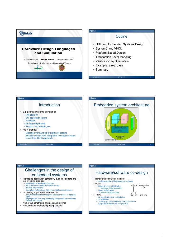
Embedded system architecture
ENVIRONMENT
MEMORY ISP HARDWIRED UNIT Application-specific logic Timers A/D and D/A Converters SENSORS ACTUATOR S
EMBEDDED SYSTEM
Challenges in the design of embedded systems
- Increasing application complexity even in standard and
large volume products
– large systems with legacy functions – mixture of event driven and data flow tasks – flexiblity requirements – examples: multimedia, automotive, mobile communication
- Increasing target system complexity
– mixture of different technologies, processor types, and design styles – large systems-on-a-chip combining components from different sources (IP market)
- Numerous constraints and design objectives
- Reduced and overlapping design cycles
Hardware/software co-design
- Hardware/software co-design:
– combined design of hardware and software
- Goals
– design process optimization
- Increased design productivity
– design optimization
- Improved product quality
- Tasks
– co-specification and co-modeling – co-verification – co-design process integration and optimization – design optimization and co-synthesis
HW SW HW SW co-design classic design