
SLIDE 1
Lecture 8
Logistics
HW2 due Friday Shorter HW3 posted--- due Monday (materials covered in midterm1)
p y ( ) sol’n out on Monday, late assignment not accepted
Verilog tutorial (overview + handout): provided with Lab 4 Schedule shift: adjustment on the web Midterm 1: Wednesday in class --- materials up to Lecture 9 Review session on Tuesday? Time?
Last lecture
K d ’t POS K
1
CSE370, Lecture 10 K-maps, don’t cares, POS K-maps
Today
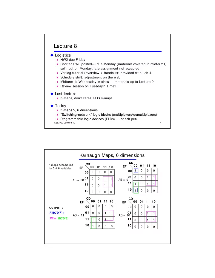
K-maps 5, 6 dimensions "Switching-network" logic blocks (multiplexers/demultiplexers) Programmable logic devices (PLDs) --- sneak peak
Karnaugh Maps, 6 dimensions
CD EF 00 01 11 10 00 01 AB = 00 1 1 CD EF 00 01 11 10 00 01 1 1 1 AB = 01
K-maps become 3D for 5 & 6 variables