previous lecture today s lecture slides for lecture 28
play

Previous Lecture Todays Lecture Slides for Lecture 28 Completion - PowerPoint PPT Presentation

ENEL 353 F13 Section 02 Slides for Lecture 28 slide 2/19 ENEL 353 F13 Section 02 Slides for Lecture 28 slide 3/19 Previous Lecture Todays Lecture Slides for Lecture 28 Completion of divide-by-3 counter FSM design using ENEL 353:


  1. ENEL 353 F13 Section 02 Slides for Lecture 28 slide 2/19 ENEL 353 F13 Section 02 Slides for Lecture 28 slide 3/19 Previous Lecture Today’s Lecture Slides for Lecture 28 Completion of “divide-by-3 counter” FSM design using ENEL 353: Digital Circuits — Fall 2013 Term one-hot state encoding. Introduction to “sequence detection” problems, and solution Review of the steps involved in designing a Moore FSM. using Moore and Mealy FSMs. Steve Norman, PhD, PEng A “divide-by-3 counter” FSM design problem, solved with Moore and Mealy state transition diagrams for an example Electrical & Computer Engineering binary state encoding, and solved again with “one-hot” sequence detection problem. Schulich School of Engineering University of Calgary encoding. Completion of next state and output logic design for the Mealy FSM. 15 November, 2013 Factoring of FSMs. Related reading in Harris & Harris: Sections 3.4.2–3.4.4 slide 4/19 slide 5/19 slide 6/19 ENEL 353 F13 Section 02 Slides for Lecture 28 ENEL 353 F13 Section 02 Slides for Lecture 28 ENEL 353 F13 Section 02 Slides for Lecture 28 Divide-by-3 counter with one-hot encoding (repeat slide) Sequence detection problems Useful assumptions for sequence detection problems One-hot state encoding requires one flip-flop for each state. In Most textbooks on digital design present several FSM design any state, a single state bit is TRUE and all the others are problems that are worded something like this example: 
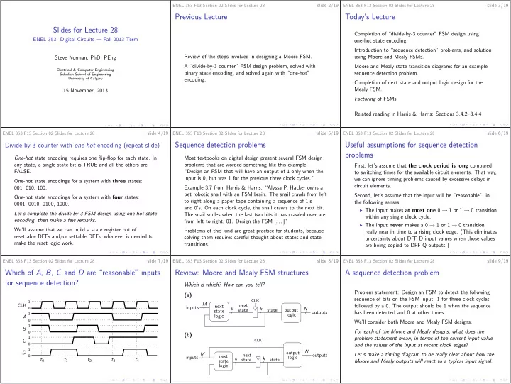
First, let’s assume that the clock period is long compared FALSE. “Design an FSM that will have an output of 1 only when the to switching times for the available circuit elements. That way, input is 0, but was 1 for the previous three clock cycles.” we can ignore timing problems caused by excessive delays in One-hot state encodings for a system with three states: circuit elements. 001, 010, 100. Example 3.7 from Harris & Harris: “Alyssa P. Hacker owns a pet robotic snail with an FSM brain. The snail crawls from left Second, let’s assume that the input will be “reasonable”, in One-hot state encodings for a system with four states: to right along a paper tape containing a sequence of 1’s the following senses: 0001, 0010, 0100, 1000. and 0’s. On each clock cycle, the snail crawls to the next bit. ◮ The input makes at most one 0 → 1 or 1 → 0 transition Let’s complete the divide-by-3 FSM design using one-hot state The snail smiles when the last two bits it has crawled over are, within any single clock cycle. encoding, then make a few remarks. from left to right, 01. Design the FSM [. . . ]” ◮ The input never makes a 0 → 1 or 1 → 0 transition We’ll assume that we can build a state register out of Problems of this kind are great practice for students, because really near in time to a rising clock edge. (This eliminates resettable DFFs and/or settable DFFs, whatever is needed to solving them requires careful thought about states and state uncertainty about DFF D input values when those values make the reset logic work. transitions. are being copied to DFF Q outputs.) ENEL 353 F13 Section 02 Slides for Lecture 28 slide 7/19 ENEL 353 F13 Section 02 Slides for Lecture 28 slide 8/19 ENEL 353 F13 Section 02 Slides for Lecture 28 slide 9/19 Which of A , B , C and D are “reasonable” inputs Review: Moore and Mealy FSM structures A sequence detection problem for sequence detection? Which is which? How can you tell? Problem statement: Design an FSM to detect the following (a) sequence of bits on the FSM input: 1 for three clock cycles CLK 1 M CLK next next followed by a 0. The output should be 1 when the sequence inputs 0 k k N state state output state outputs has been detected and 0 at other times. 1 logic logic A 0 We’ll consider both Moore and Mealy FSM designs. 1 B For each of the Moore and Mealy designs, what does the 0 (b) 1 problem statement mean, in terms of the current input value C CLK 0 and the values of the input at recent clock edges? 1 D output N inputs M next outputs Let’s make a timing diagram to be really clear about how the 0 next logic t 0 t 1 t 2 t 3 t 4 k state k state state Moore and Mealy outputs will react to a typical input signal. logic

  2. ENEL 353 F13 Section 02 Slides for Lecture 28 slide 10/19 ENEL 353 F13 Section 02 Slides for Lecture 28 slide 11/19 ENEL 353 F13 Section 02 Slides for Lecture 28 slide 12/19 Sequence detection example: Moore FSM Sequence detection example: Mealy FSM Sequence detection example: Mealy FSM, continued Let’s make a list of states appropriate for a Mealy FSM Let’s choose unsigned binary encoding of the states. Let’s describe the states of the system. solution to the problem. Let’s make a combined state transition and output table. Let’s make a state transition diagram. Let’s make a state transition diagram. (We’ll go straight to the version that is based on our chosen state encoding, because it’s pretty easy to do without a In order to give more time to the Mealy FSM design problem, Let’s make some general notes about how state transition version that lists the states symbolically.) we won’t complete the Moore FSM design work. diagrams for Mealy FSMs differ from state transition diagrams for Moore FSMs. Let’s find next-state and output equations. Let’s draw a schematic. slide 13/19 slide 14/19 slide 15/19 ENEL 353 F13 Section 02 Slides for Lecture 28 ENEL 353 F13 Section 02 Slides for Lecture 28 ENEL 353 F13 Section 02 Slides for Lecture 28 Sequence detection FSMs with an “unreasonable” A revised traffic light problem Revised traffic light problem: Most obvious FSM input signal solution N B. Blvd In regular mode , the system behaves like the Let’s determine what the Moore and Mealy FSMs will do if W E system that’s already the input A is as shown . . . S been designed. One approach to the problem is to make a new design with 1 eight states: CLK In parade mode , the 0 A. Ave ◮ four states for regular mode; system advances through 1 reset 0 the regular sequence ◮ four more states for parade mode. 1 A until it gets to red for A Why are four different states needed for parade mode? 0 and green for B, then 1 Y (Moore) The eight-state FSM idea leads to the messy state transition stays in that state . 0 1 diagram on the next slide . . . Y (Mealy) 0 t 0 t 1 t 2 t 3 t 4 Let’s make a block diagram showing the inputs and outputs of the new, more complex traffic light controller. Let’s make a few remarks. 8-state transition diagram for traffic light system with ENEL 353 F13 Section 02 Slides for Lecture 28 slide 17/19 ENEL 353 F13 Section 02 Slides for Lecture 28 slide 18/19 “parade mode” Factoring FSMs State transition diagrams for factored FSM design P T A P T A T A R T A R T A The parade-mode example is set up to make two main points: Reset Reset T A S0 P T A S1 S0 S1 R T A ◮ Trying to solve every synchronous sequential problem with R T A L A : green L A : yellow S4 S5 L A : green L A : yellow P L B : red L B : red L B : red L B : red L A : green L A : yellow a single FSM may result in unreasonably complex FSM L B : red L B : red R P designs. P T A P R ◮ FSMs are nevertheless a great design tool. Sometimes it P P R Reset P T B R make sense to design a system as a collection of simple, P S3 S2 S3 S2 S0 S1 L A : red L A : red S7 S6 L A : red L A : red collaborating FSMs. M: 0 M: 1 L B : yellow L B : green L A : red L A : red L B : yellow L B : green P T B L B : yellow L B : green R MT B Factoring is the name given to the approach described in the P R M + T B R second of the above two points. Lights FSM Mode FSM R T B R T B Let’s draw a block diagram to show how the traffic light Image is taken from Figure 3.34 from Harris D. M. and Harris S. L., controller with parade mode can be designed using two simple Digital Design and Computer Architecture, 2nd ed. , c Image is taken from Figure 3.34 from Harris D. M. and Harris S. L., � 2013, Elsevier, FSMs that work together. Digital Design and Computer Architecture, 2nd ed. , c � 2013, Elsevier, Inc. Inc.

  3. ENEL 353 F13 Section 02 Slides for Lecture 28 slide 19/19 Upcoming topics Reverse-engineering an FSM: Given a circuit, find a word description of what the FSM does. Timing of sequential logic. Related reading in Harris & Harris: Sections 3.4.5–3.4.6, Section 3.5 up to the end of 3.5.2.

Download Presentation
Download Policy: The content available on the website is offered to you 'AS IS' for your personal information and use only. It cannot be commercialized, licensed, or distributed on other websites without prior consent from the author. To download a presentation, simply click this link. If you encounter any difficulties during the download process, it's possible that the publisher has removed the file from their server.

Recommend


More recommend