
SLIDE 1
Slides for Lecture 30
ENEL 353: Digital Circuits — Fall 2013 Term Steve Norman, PhD, PEng Electrical & Computer Engineering Schulich School of Engineering University of Calgary 20 November, 2013 ENEL 353 F13 Section 02 Slides for Lecture 30 slide 2/21Previous Lecture
Completion of next-state and output logic design for the Mealy FSM solution to example sequence detection problem. Factoring of FSMs. Reverse-engineering an FSM: Given an FSM circuit, finding a word description of what the FSM does. ENEL 353 F13 Section 02 Slides for Lecture 30 slide 3/21Today’s Lecture
Completion of an FSM reverse-engineering example. Introduction to timing of sequential logic. Timing parameters for DFFs, and implications of those parameters for timing of synchronous sequential circuits. Related reading in Harris & Harris: Sections 3.4.5–3.4.6, Section 3.5 to the end of 3.5.2. slide 4/21 (This picks up from where the previous lecture ended.) The next three steps are: ◮ Use next-state and output equations to create next-state and output tables. (The next-state table is ready for us on this slide, to save us all some boredom.) ◮ Reduce the next-state table to eliminate unreachable states. ◮ Assign each valid state bit combination a name. Let’s perform the last two of the above steps. S2 S1 S0 A S′ 2 S′ 1 S′ 1 1 1 1 1 1 1 1 1 1 1 1 1 1 1 1 1 1 1 1 1 1 1 1 1 1 1 1 1 1 1 1 1 1 1 1 1 1 1 1 1 1 ENEL 353 F13 Section 02 Slides for Lecture 30 slide 5/21Completion of the example FSM derivation problem
The final three steps are: ◮ Rewrite next-state and output tables with state names. ◮ Draw state transition diagram. ◮ State in words what the FSM does. Let’s work through these steps. ENEL 353 F13 Section 02 Slides for Lecture 30 slide 6/21Introduction to timing of sequential logic
For a synchronous sequential circuit design, some of the major timing concerns are . . . ◮ What are sufficient conditions on the D input of a DFF to ensure reliable operations of the DFF? (This is called the “dynamic discipline”.) ◮ Given timing specifications for DFFs and a desired clock period TC, what do those things say about maximum delays in combinational elements in the circuit? ◮ What can go wrong if D inputs of DFFs go 0 → 1 or 1 → 0 at the wrong time? Section 3.5 of Harris & Harris is excellent on these topics. Please read it carefully, more than once! ENEL 353 F13 Section 02 Slides for Lecture 30 slide 7/21Review: The static discipline
This idea was introduced very early in the course. (See Section 1.6 of Harris and Harris.) The static discipline says that for reliable operation of digital circuit elements, voltages on inputs of circuit elements must not sit in the forbidden zone between VIL and VIH. (Of course, voltages are allowed to pass through the forbidden zone when making low-to-high or high-to-low transitions!) ENEL 353 F13 Section 02 Slides for Lecture 30 slide 8/21The dynamic discipline
The dynamic discipline has to do with rules about the timing- f transitions on input signals to sequential devices such as
- r 1 → 0 transition within an aperture time
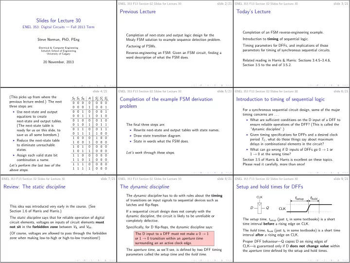
Setup and hold times for DFFs
D Q CLK CLKtsetup thold
The setup time, tsetup (just ts in some textbooks) is a short time interval before a rising edge on CLK. The hold time, thold (just th in some textbooks) is a short time interval after a rising edge on CLK. Proper DFF behaviour—Q copies D on rising edges of CLK—is guaranteed only if D does not change value within the aperture time defined by the setup and hold times.