previous lecture today s lecture slides for lecture 6
play

Previous Lecture Todays Lecture Slides for Lecture 6 ENEL 353: - PowerPoint PPT Presentation

ENEL 353 F13 Section 02 Slides for Lecture 6 slide 2/21 ENEL 353 F13 Section 02 Slides for Lecture 6 slide 3/21 Previous Lecture Todays Lecture Slides for Lecture 6 ENEL 353: Digital Circuits Fall 2013 Term ranges for


  1. ENEL 353 F13 Section 02 Slides for Lecture 6 slide 2/21 ENEL 353 F13 Section 02 Slides for Lecture 6 slide 3/21 Previous Lecture Today’s Lecture Slides for Lecture 6 ENEL 353: Digital Circuits — Fall 2013 Term ◮ ranges for two’s-complement systems A little more about Gray codes. Steve Norman, PhD, PEng ◮ overflow in two’s-complement addition Introduction to logic gates. Electrical & Computer Engineering ◮ BCD (binary coded decimal) codes for decimal digits Schulich School of Engineering University of Calgary ◮ Gray codes Related reading in Harris & Harris: Section 1.5 20 September, 2013 slide 4/21 slide 6/21 ENEL 353 F13 Section 02 Slides for Lecture 6 A 4-bit shaft encoder : Optical sensors make a digital measurement ENEL 353 F13 Section 02 Slides for Lecture 6 o
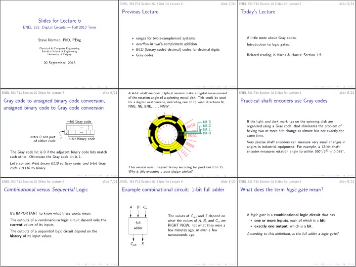
f the rotation angle of a spinning metal disk. This could be used Gray code to unsigned binary code conversion, Practical shaft encoders use Gray codes for a digital weathervane, indicating one of 16 wind directions N, unsigned binary code to Gray code conversion NNE, NE, ENE, . . . , NNW. n -bit Gray code If the light and dark markings on the spinning disk are organized using a Gray code, that eliminates the problem of ... having two or more bits change at almost but not exactly the 0 ... same time. extra 0 not part n -bit binary code of either code Very precise shaft encoders can measure very small changes in angles in industrial equipment. For example, a 12-bit shaft encoder measures rotation angle to within 360 ◦ / 2 12 = 0 . 088 ◦ . The Gray code bit is 0 if the adjacent binary code bits match each other. Otherwise the Gray code bit is 1. Let’s convert 4-bit binary 0110 to Gray code, and 6-bit Gray code 101110 to binary. This version uses unsigned binary encoding for positions 0 to 15. Why is this encoding a poor design choice? ENEL 353 F13 Section 02 Slides for Lecture 6 slide 7/21 ENEL 353 F13 Section 02 Slides for Lecture 6 slide 8/21 ENEL 353 F13 Section 02 Slides for Lecture 6 slide 9/21 Combinational versus Sequential Logic Example combinational circuit: 1-bit full adder What does the term logic gate mean? A B C in It’s IMPORTANT to know what these words mean. A logic gate is a combinational logic circuit that has The values of C out and S depend on The outputs of a combinational logic circuit depend only the what the values of A , B , and C in are ◮ one or more inputs , each of which is a bit ; full current values of its inputs. RIGHT NOW, not what they were a ◮ exactly one output , which is a bit . adder few minutes ago, or even a few The outputs of a sequential logic circuit depend on the nanoseconds ago. According to this definition, is the full adder a logic gate? history of its input values. C out S

  2. ENEL 353 F13 Section 02 Slides for Lecture 6 slide 10/21 ENEL 353 F13 Section 02 Slides for Lecture 6 slide 11/21 ENEL 353 F13 Section 02 Slides for Lecture 6 slide 12/21 Graphical and algebraic notations for some 1-input gates An alternate notation for the NOT operation common 1- and 2-input logic gates A NOT gate, also called an inverter : The “overline” is probably the most common notation for the A Y = A A A Y = A NOT operation, but there is another symbol in wide use. Y = A ⊕ B B In A is the input and Y is the output. The “bubble” in the Many textbooks and other documents use the ′ symbol A Y = A A symbol indicates inversion: 0 converted to 1, and 1 converted Y = AB (“prime”) instead. This includes the textbook used last year in to 0. The equation Y = A is read, “Y equals NOT A.” B A ENEL 353. Y = AB A A buffer : B Y = A + B This year we will use an “overline” for the NOT operation, to B A A Y = A be consistent with this year’s textbook. Y = A + B A B If you see A ′ in course material from past years, translate that Y = A ⊕ B The output Y is just a copy of the input A . Logically this is B no different from a wire, but electrically, a buffer can help with in your head to A . We’ll now examine these gates one or two at a time . . . circuit timing, making sure a device gets enough input current, and so on. slide 13/21 slide 14/21 slide 15/21 ENEL 353 F13 Section 02 Slides for Lecture 6 ENEL 353 F13 Section 02 Slides for Lecture 6 ENEL 353 F13 Section 02 Slides for Lecture 6 Truth tables When writing in English about logic gates, The AND gate use ALL CAPS for the names of gates Here is the symbol and the algebraic notation: A Y = AB B A truth table describes a combinational logic element by making a list of the values of the output for all possible One way to remember the symbol is to remember that the Confusing: “For this design you may use or or and gates but word AND contains a D, and the symbol looks like a D. combinations of input bits. not not gates.” An alternate algebraic notation for AND uses the · symbol, as (We’ve already seen the truth table for the 1-bit full adder.) Better: “For this design you may use OR or AND gates but in Y = A · B . Let’s write out the very simple truth tables for a NOT gate not NOT gates.” and a buffer. Here is how the AND operation is defined: � 1 if both A and B are 1 AB = 0 otherwise Let’s write the truth table for AND . ENEL 353 F13 Section 02 Slides for Lecture 6 slide 16/21 ENEL 353 F13 Section 02 Slides for Lecture 6 slide 17/21 ENEL 353 F13 Section 02 Slides for Lecture 6 slide 18/21 The OR gate In discussion of digital logic, The XOR gate + does not mean arithmetic addition Symbol and algebraic notation . . . XOR is short for exclusive OR . A A Y = A + B Y = A ⊕ B B B ◮ In decimal arithmetic, what is 1 + 1 ? Here is how the OR operation is defined: “Exclusive or” means “one or the other but not both .” ◮ In binary arithmetic, what is 1 + 1 ? � 0 if both A and B are 0 ◮ In digital logic, what is 1 + 1 ? A + B = � 1 1 otherwise if one of A and B is 1 and the other is 0 This can be confusing, especially when discussing digital logic A ⊕ B = 0 otherwise circuits that are designed to do arithmetic! In other words, in digital logic, OR means “one or the other or both are true.” Let’s write the truth table for XOR . Let’s write the truth table for OR .

  3. ENEL 353 F13 Section 02 Slides for Lecture 6 slide 19/21 ENEL 353 F13 Section 02 Slides for Lecture 6 slide 20/21 ENEL 353 F13 Section 02 Slides for Lecture 6 slide 21/21 Convention for ordering of truth table input Convention for ordering of truth table input Next Lecture combinations combinations: Examples This follows the These two tables convey the same information, but should be AVOIDED! convention . . . More 2-input gates: NAND, NOR and XNOR. ◮ Start with the row for all inputs = 0. A B C Y A B C Y A B C Y ◮ Alternate 0’s and 1’s most slowly on the left. Examples of gates with 3 or more inputs. 0 0 0 0 1 1 1 1 0 0 0 0 ◮ Alternate 0’s and 1’s more quickly as you move left to Correspondences between bit values and voltage levels in 0 0 1 0 1 1 0 1 1 0 0 0 right. digital circuits. 0 1 0 0 1 0 1 1 0 1 0 0 ◮ Alternate 0’s and 1’s most quickly—every row—on the 0 1 1 0 1 0 0 0 1 1 0 1 right. 1 0 0 0 Related reading in Harris & Harris: Sections 1.5 and 1.6. 0 1 1 0 0 0 1 0 ◮ In other words, write the input bit patterns in unsigned 1 0 1 1 0 1 0 0 1 0 1 1 binary ordering. 1 1 0 1 0 0 1 0 0 1 1 0 1 1 1 1 0 0 0 0 1 1 1 1

Download Presentation
Download Policy: The content available on the website is offered to you 'AS IS' for your personal information and use only. It cannot be commercialized, licensed, or distributed on other websites without prior consent from the author. To download a presentation, simply click this link. If you encounter any difficulties during the download process, it's possible that the publisher has removed the file from their server.

Recommend


More recommend