previous lecture today s lecture slides for lecture 26
play

Previous Lecture Todays Lecture Slides for Lecture 26 ENEL 353: - PowerPoint PPT Presentation

ENEL 353 F13 Section 02 Slides for Lecture 26 slide 2/19 ENEL 353 F13 Section 02 Slides for Lecture 26 slide 3/19 Previous Lecture Todays Lecture Slides for Lecture 26 ENEL 353: Digital Circuits Fall 2013 Term Detailed discussion of


  1. ENEL 353 F13 Section 02 Slides for Lecture 26 slide 2/19 ENEL 353 F13 Section 02 Slides for Lecture 26 slide 3/19 Previous Lecture Today’s Lecture Slides for Lecture 26 ENEL 353: Digital Circuits — Fall 2013 Term 
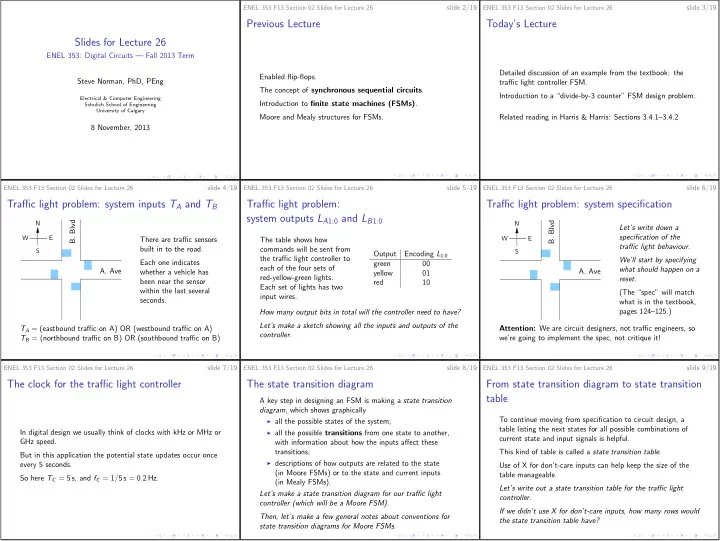
Detailed discussion of an example from the textbook: the Enabled flip-flops. Steve Norman, PhD, PEng traffic light controller FSM. The concept of synchronous sequential circuits . Introduction to a “divide-by-3 counter” FSM design problem. Electrical & Computer Engineering Introduction to finite state machines (FSMs) . Schulich School of Engineering University of Calgary Moore and Mealy structures for FSMs. Related reading in Harris & Harris: Sections 3.4.1–3.4.2 8 November, 2013 slide 4/19 slide 5/19 slide 6/19 ENEL 353 F13 Section 02 Slides for Lecture 26 ENEL 353 F13 Section 02 Slides for Lecture 26 ENEL 353 F13 Section 02 Slides for Lecture 26 Traffic light problem: system inputs T A and T B Traffic light problem: Traffic light problem: system specification system outputs L A 1:0 and L B 1:0 N B. Blvd B. Blvd N Let’s write down a specification of the W E W E There are traffic sensors The table shows how traffic light behaviour. built in to the road. commands will be sent from S S Output Encoding L 1:0 the traffic light controller to We’ll start by specifying Each one indicates green 00 each of the four sets of A. Ave what should happen on a whether a vehicle has yellow 01 A. Ave red-yellow-green lights. reset. been near the sensor red 10 Each set of lights has two within the last several (The “spec” will match input wires. seconds. what is in the textbook, How many output bits in total will the controller need to have? pages 124–125.) Let’s make a sketch showing all the inputs and outputs of the T A = (eastbound traffic on A) OR (westbound traffic on A) Attention: We are circuit designers, not traffic engineers, so controller. T B = (northbound traffic on B) OR (southbound traffic on B) we’re going to implement the spec, not critique it! ENEL 353 F13 Section 02 Slides for Lecture 26 slide 7/19 ENEL 353 F13 Section 02 Slides for Lecture 26 slide 8/19 ENEL 353 F13 Section 02 Slides for Lecture 26 slide 9/19 The clock for the traffic light controller The state transition diagram From state transition diagram to state transition table A key step in designing an FSM is making a state transition diagram , which shows graphically To continue moving from specification to circuit design, a ◮ all the possible states of the system; table listing the next states for all possible combinations of ◮ all the possible transitions from one state to another, In digital design we usually think of clocks with kHz or MHz or current state and input signals is helpful. GHz speed. with information about how the inputs affect these transitions; This kind of table is called a state transition table . But in this application the potential state updates occur once ◮ descriptions of how outputs are related to the state every 5 seconds. Use of X for don’t-care inputs can help keep the size of the (in Moore FSMs) or to the state and current inputs table manageable. So here T C = 5 s, and f C = 1 / 5 s = 0 . 2 Hz. (in Mealy FSMs). Let’s write out a state transition table for the traffic light Let’s make a state transition diagram for our traffic light controller. controller (which will be a Moore FSM). If we didn’t use X for don’t-care inputs, how many rows would Then, let’s make a few general notes about conventions for the state transition table have? state transition diagrams for Moore FSMs.

  2. ENEL 353 F13 Section 02 Slides for Lecture 26 slide 10/19 ENEL 353 F13 Section 02 Slides for Lecture 26 slide 11/19 ENEL 353 F13 Section 02 Slides for Lecture 26 slide 12/19 State encoding A truth table for next state logic Output logic for the traffic light controller In our FSM circuit, the state will be stored in DFFs in a register, so to make further progress, we will need to decide on By substituting our state encodings into the state transition To design output logic, we need to combine the information bit patterns to represent each of the states that we have table, we can get a version of the state transition table that below into a truth table. named S0, S1, S2, and S3. completely specifies the next state as a combinational logic State, S 1:0 Desired lights Output L 1:0 function of the current state and input variables. S0, 00 green on A, red on B Let’s write out the most obvious choice of state encoding for green 00 the traffic light controller example. Let’s make that table for the traffic light controller. S1, 01 yellow on A, red on B yellow 01 S2, 10 red on A, green on B Important remark about notation: Let’s use the table and some K-maps to find equations for S ′ red 10 1 S3, 11 red on A, yellow on B ◮ S0, S1, S2, S3 (with digits the same size as letters) are and S ′ 0 . (Harris and Harris go straight from the table to Let’s make the truth table, then use it to get equations for equations, but your instructor thinks K-maps help to explain names of states . L A 1 , L A 0 , L B 1 , and L B 0 . where the equations come from.) ◮ S 0 and S 1 (with digits appearing in subscripts) identify bits within the state register . slide 13/19 slide 14/19 slide 15/19 ENEL 353 F13 Section 02 Slides for Lecture 26 ENEL 353 F13 Section 02 Slides for Lecture 26 ENEL 353 F13 Section 02 Slides for Lecture 26 From equations to a circuit . . . Review: General structure of a Moore FSM Moore FSM structure of traffic light controller CLK L A 1 CLK S ′ S 1 L A 1 1 S ′ S 1 1 L A 0 CLK M next next inputs L A 0 k k N T A state state output state S ′ S 0 outputs 0 logic L B 1 logic T A r S ′ S 0 0 L B 1 T B r reset T B ¯ ¯ L B 0 S 1 S 1 S 0 S 0 reset L B 0 It’s not hard to see how the traffic light controller fits into this framework . . . S 0 output logic The schematics in Figure 3.26 in Harris & Harris are a more S 1 next state logic compact way of representing this particular implementation of the traffic light controller. ENEL 353 F13 Section 02 Slides for Lecture 26 slide 16/19 ENEL 353 F13 Section 02 Slides for Lecture 26 slide 17/19 ENEL 353 F13 Section 02 Slides for Lecture 26 slide 18/19 Timing diagram for the traffic light controller FSM Next FSM Example: A “divide-by-3 counter” Divide-by-3 counter: Waveforms and a state transition diagram This example is taken from Section 3.4.2 of Harris & Harris. CLK Figure 3.27 on page 128 of Harris & Harris is an excellent We’ll use the example Y timing diagram showing behaviour of the FSM over ten ◮ to review the steps in designing an FSM, starting from a (a) example clock cycles. word description of system behaviour; Reset There’s too much detail in the diagram to make a legible slide ◮ to illustrate how the choice of state encoding may from it. influence the relative complexity of next state and output S0 S1 S2 Y : 1 Y : 0 Y : 0 logic. Please study the diagram and the related discussion on pages 127 and 129 carefully! It really helps in explaining typical FSM Word description of the divide-by-3 counter: The only operation as time progresses. inputs are clock and reset signals. The output should be 1 (b) during every third cycle of the input clock, and 0 during other Image is taken from Figure 3.28 from Harris D. M. and Harris S. L., cycles of the input clock. Digital Design and Computer Architecture, 2nd ed. , c � 2013, Elsevier, Inc.

  3. ENEL 353 F13 Section 02 Slides for Lecture 26 slide 19/19 Upcoming topics Completion of two different divide-by-3 counter designs, and discussion of binary versus one-hot state encoding. Mealy FSM design examples. Factoring of FSMs. Reverse-engineering an FSM: Given a circuit, find a word description of what the FSM does. Related reading in Harris & Harris: Sections 3.4.2–3.4.6.

Download Presentation
Download Policy: The content available on the website is offered to you 'AS IS' for your personal information and use only. It cannot be commercialized, licensed, or distributed on other websites without prior consent from the author. To download a presentation, simply click this link. If you encounter any difficulties during the download process, it's possible that the publisher has removed the file from their server.

Recommend


More recommend