
SLIDE 1
Speaker: Mrs Gina Stefanakou Deputy Director WWTP Division & Head of Psyttalia WWTP Department EYDAP S.A., www.eydap.gr
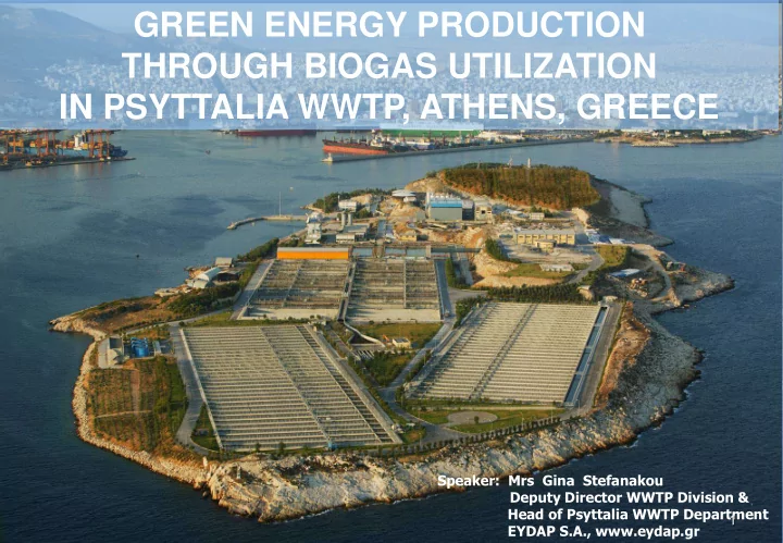
GREEN ENERGY PRODUCTION THROUGH BIOGAS UTILIZATION IN PSYTTALIA WWTP, ATHENS, GREECE
1
THROUGH BIOGAS UTILIZATION IN PSYTTALIA WWTP, ATHENS, GREECE - - PowerPoint PPT Presentation
GREEN ENERGY PRODUCTION THROUGH BIOGAS UTILIZATION IN PSYTTALIA WWTP, ATHENS, GREECE Speaker: Mrs Gina Stefanakou Deputy Director WWTP Division & Head of Psyttalia WWTP Department 1 EYDAP S.A., www.eydap.gr EYDAP S.A. Athens
Speaker: Mrs Gina Stefanakou Deputy Director WWTP Division & Head of Psyttalia WWTP Department EYDAP S.A., www.eydap.gr
1
2
Serves the population of Athens metropolitan area with
Water services 4 Water treatment plants (Galatsi, Menidi, Kiourka, Aspropyrgos) 8.400 km of water distribution network Wastewater collection 6.000 km of sewer network Wastewater treatment 2 plants in operation (Psyttalia, Metamorphosis) 1 plant in test operation (Thriassio WWTP - West Attica) 5 plants in design phase (Peania-Kropia WWTP, N. Makri-Marathon WWTP, North Mesogaea WWTP, Lavreotiki WWTP & Fokea WWTP - East Attica)
3
Akrokeramos installations Psyttalia island Salamina installations Port of Piraeus
4
5
Wastewater pretreatment unit on Salamina Island and submerged
Two cogeneration plants for heat and power (CHP) utilizing biogas
One CHP plant utilizing natural gas (2009)
6
7
8
Psyttalia WWTP Flow - diagram
ELECTRIC ENERGY BIOGAS THERMAL ENERGY NATURAL GAS ELECTRIC ENERGY THERMAL ENERGY DRIED SLUDGE UTILIZATION EFFLUENT SLUDGE PUMPING GRAVITY THICKENING (TANKS) DIGESTION WASTEWATER INFLOW PUMPING COGENERATION (BIOGAS) DRYING SCREENING GRIT REMOVAL PRIMARY SEDIMENTATION DEWATERING MECHANICAL THICKENING (BELTS) FINAL SETTLING TANKS BIOREACTORS COGENERATION (NATURAL GAS)
8
9
Wastewater Pretreatment
Debris Removal Screening Grit Removal Odor Control Twin inverted siphon
9
Inlet Pumping Station 9 Archimedes Screw Pumps capacity 3m3/sec each, total capacity 27 m3/sec Pretreatment Screening 6 pairs of screens (30 / 10 mm) Grit removal 6 aerated spiral-flow channels Odor control (sodium hydroxide and sodium hypochlorite solutions, air treatment capacity 140 000 m3/h) Wastewater transport to Psyttalia through twin inverted siphon system
10
Wastewater pretreatment (Salamina island) Population served 7 000 (start of operation), 32 000 (full service) Flow-rate Peak 700 l/s Average (full service) 7000 m3/day Pretreatment Screening: Screen (20 mm) Grit removal: Aerated spiral-flow channel (retention time 3 min) Wastewater transport to Psyttalia through twin pipe system Current status of operation: Limited flow, pending further service connections
11
Wastewater Inlet Channel Primary Treatment Biological Treatment Final Settling Filtration C.H.P. Gas-holders Sludge Thermal Drying Sludge Digesters
12
Primary sedimentation 6 tanks (combined area 12 000 m2) Biological treatment 12 bioreactors (combined volume 300 000 m3) Organic load removal and nitrogen reduction Final settling 64 rectangular tanks (combined area 52 000 m2) Filtration - Disinfection 3 sand-filters (one spare; com. capacity 1500 m3/h) and mechanical filters 2 UV disinfection units Production of process water, for use in facilities on Psyttalia Outfall system Two main pipes (1870 m long each, depth 65m) Receiving waters: Inner Saronikos Gulf
13
14
15
Thickening Primary sludge gravity thickening Surplus activated sludge thickening Sludge mixing Digestion Dewatering Thermal drying Biosolids : Organic products of municipal wastewater treatment that can be beneficially used.
16
Primary sludge: Fine screening Six screens (5 mm gaps) Gravity thickening facilitated / aided by use of polyelectrolyte solution 3 tanks (combined area 1500 m2) Odor control unit (2 lines) Waste activated sludge: Mechanical thickening aided by polyelectrolyte 14 belt thickeners (comb. capacity: 1750 m3/h) Sludge in-pipe mixing prior to digestion
17
18
19
Carbohydrates Proteins Lipids Phosphorylated Organics Glucose Amino-acids Fatty Acids Phosphates (PO4
Acetic Acid Propionic Acid Lactic Acid Cells (Biomass) Cells (Biomass) Stabilized Organic Compounds
Extracellular enzymes Acid-producing microorganisms Methane-producing microorganisms
Complex Organic Compounds
Hydrolysis
Soluble Organic Compounds
Acids Formation
Organic Acids
Methane Formation
Phase A digesters: 4 Heating and mixing: 6 heat-a-mix units in each tank Phase B digesters: 4 Heating: external heat exchangers Mixing: top-mounted hanging lances
20
21
22
Decanter characteristics
22 22
23
Cogeneration plant for Heat and Power production (CHP) utilizing natural gas (gas-turbine)
Hot gases Granular sludge Dried granules and water-vapor carrying gases
24
25
25
26
27
PSYTTALIA WWTP
NATIONAL GRID MANAGER
SLUDGE THERMAL DRYING
CHP PLANTS
BIOGAS
GAS-HOLDER GAS-HOLDER BURNERS BOILER DIGESTER HEATING HEAT EXCHANGER
ELECTRIC ENERGY
ON-SITE CONSUMPTION ENERGY SALE
DIGESTER HEATING CLOSED CIRCUIT HEAT
SLUDGE D I G E S T E R BIOGAS PRODUCTION IN DIGESTERS BIOGAS STORAGE IN GAS HOLDERS U T I L I S Α T I O N
28
29
29
30
31
32
GAS - HOLDERS
ELECTRIC ENERGY THERMAL ENERGY THERMAL ENERGY
DIGESTERS
CONSUMPTION ON-SITE SALE TO NATIONAL GRID ELECTRIC ENERGY SALE TO NATIONAL GRID
BIOGAS UTILIZATION AS FUEL IN CHP PLANTS FOR ELECTRIC POWER AND HEAT PRODUCTION
CHP PLANT 7,14 ΜWe
Phase A’
Power grid
Phase B’
Power grid Power supply to Phase B’ installations at Psyttalia WWTP Commisioning 2001 Commisioning 2009 Power supply to Phase A’ installations at Psyttalia WWTP
Electric energy surplus Electric energy surplus
CHP PLANT 4,25 ΜWe 33
CONSUMPTION ON-SITE
33
Number of Gas-Engines
Mechanical Power
Electrical Power Capacity
Heat Capacity
Number of Pistons
Frequency 1 000 rpm Peak Biogas Consumption
Biogas Inflow Pressure
Fuel Pressure (Biogas after compression) 3.2 bar Generators Capacity
Generators Output Voltage 3 300 V Electric Current Frequency 50 Hz Voltage to Grid
34
7.14 MWe CHP PLANT FLOW DIAGRAM
35
Biogas Psyttalia WWTP Psyttalia WWTP Power Mechanical Electrical Grid Energy Energy Heat Flue Gases Gas Engine Generator Combustion Power Production Compression Digestion Dehumidi- fication Psyttalia Substation Akrokeramos Substation Storage Cleaning
Number of Gas-Engines
Mechanical Power
Electrical Power Capacity
Heat Capacity
Number of Pistons
Frequency 1 500 rpm Peak Biogas Consumption
Biogas Inflow Pressure
Fuel Pressure (Biogas after compression) 40 mbar Generators Capacity
Generators Output Voltage 3 300 V Electric Current Frequency 50 Hz Voltage to Grid
36
Internal Combustion Engine G
Biological stage for Hydrogen Sulfide removal Chemical Stage
Biogas Ο2
Nutrients
Ο2 NaOH
Replenishment
Η2S
Activated Carbon Filter
Gas-engine Feed Gas-holders
Biogas
Measurement Biological Stage Control Measurement Chemical Stage Control
Biological Desulphurization Unit
Process Water
Generator
Biological Desulphurization Unit 4,25 MWe CHP Plant
Nitrates Nitrogenous substances
37
38
39