
SLIDE 1
dt10 2011 4.1
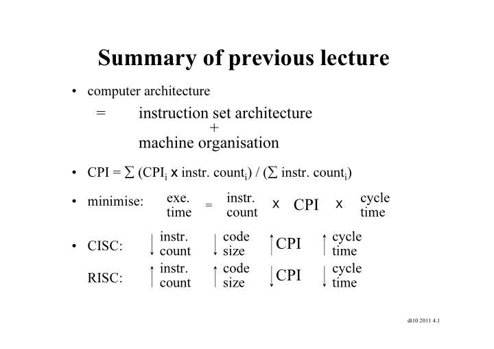
Summary of previous lecture
- computer architecture
- CPI = ∑ (CPIi x instr. counti) / (∑ instr. counti)
- minimise:
- CISC:
RISC:
= instruction set architecture + machine organisation
exe. time instr. count cycle time
CPI
X X