SLIDE 1
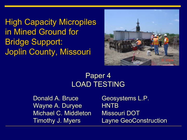
High Capacity Micropiles High Capacity Micropiles in Mined Ground for in Mined Ground for Bridge Support: Bridge Support: Joplin County, Missouri Joplin County, Missouri
Paper 4 Paper 4 LOAD TESTING LOAD TESTING
Geosystems L.P. Geosystems L.P. HNTB HNTB Missouri DOT Missouri DOT Layne GeoConstruction Layne GeoConstruction Donald A. Bruce Donald A. Bruce Wayne A. Duryee Wayne A. Duryee Michael C. Middleton Michael C. Middleton Timothy J. Myers Timothy J. Myers
SLIDE 2 Scope Scope
1.
Introduction 2.
- 2. Technical Requirements
Technical Requirements 2.1 2.1 Specifications Specifications 2.2.1 2.2.1 Verification Load Tests Verification Load Tests 2.1.2 2.1.2 Proof Tests Proof Tests 2.2 2.2 Contractor’s Conforming Submittal Contractor’s Conforming Submittal 3.
- 3. Results of Verification Tests (4)
Results of Verification Tests (4) -
(Paper 2: Foster, Peters, Bruce, Chuaqui and Norrish) Peters, Bruce, Chuaqui and Norrish) 4.
- 4. Results of the Proof Tests (16)
Results of the Proof Tests (16) 5.
Final Observations
SLIDE 3
2. 2. Technical Requirements Technical Requirements 2.1 2.1 Specifications Specifications
– – Minimum
Minimum anticipated anticipated cased and bond zone cased and bond zone lengths provided per pile. lengths provided per pile.
– – Minimum load requirements provided per pile.
Minimum load requirements provided per pile.
– – GBR bond values to be verified by 4
GBR bond values to be verified by 4 preproduction Verification piles, and directed preproduction Verification piles, and directed thereafter by the Engineer. thereafter by the Engineer.
– – Contractor to design and conduct load tests and
Contractor to design and conduct load tests and collect all load/movement data. collect all load/movement data.
– – Proof testing of production piles: one per each of
Proof testing of production piles: one per each of the 16 bents to 1.2 DL. the 16 bents to 1.2 DL.
SLIDE 4 2.1.1 Verification Load Tests: Summary 2.1.1 Verification Load Tests: Summary
– – 4 vertical piles in different ground conditions.
4 vertical piles in different ground conditions.
– – Test cyclically to 2.0 DL.
Test cyclically to 2.0 DL.
– – Conduct creep tests.
Conduct creep tests.
– – No acceptance criteria, i.e., no pass
No acceptance criteria, i.e., no pass-
fail.
SLIDE 5
Actual Verification Pile Dimensions and Ground Conditions
SLIDE 6
Details of Verification Pile Testing Details of Verification Pile Testing
SLIDE 7 2.1.2 Proof Tests 2.1.2 Proof Tests
– –
Total of 220 production piles (vertical and inclined). Total of 220 production piles (vertical and inclined).
– –
16 Proof Tests 16 Proof Tests – – locations at each bent to be selected in locations at each bent to be selected in the field by the Engineer. the field by the Engineer.
– –
Simple incremental tensile loading to 1.2 DL, with 60 Simple incremental tensile loading to 1.2 DL, with 60-
- minute creep test (Modified ASTM D3689 Quick Test).
minute creep test (Modified ASTM D3689 Quick Test).
– –
Acceptance criteria: Acceptance criteria: 1.
No failure at TL. 2.
- 2. Debonding at TL ≤ 50% bond length.
Debonding at TL ≤ 50% bond length. 3.
- 3. Creep rate ≤ 1 mm per log cycle (1
Creep rate ≤ 1 mm per log cycle (1-
10 mins.) or ≤ 2mm per log cycle (6 per log cycle (6-
60 mins.).
– –
If failure occurs, test another pile in the same bent, and If failure occurs, test another pile in the same bent, and consider modifications, down rating, replacement, etc. consider modifications, down rating, replacement, etc.
– –
Each test paid for on lump Each test paid for on lump-
sum basis.
SLIDE 8
2.2 Contractor’s Conforming Submittal 2.2 Contractor’s Conforming Submittal
SLIDE 9
Tension Test Setup Tension Test Setup
SLIDE 10
Load Testing in Progress
SLIDE 11
- 4. Results of the Proof Tests
- 4. Results of the Proof Tests
– – Every micropile reached the test loads (986
Every micropile reached the test loads (986-
2,269 kN). kN).
– – At TL debonded lengths were exceptionally small
At TL debonded lengths were exceptionally small and in only one case did it extend beyond the and in only one case did it extend beyond the cased length. cased length.
– – Permanent movements at TL ranged from 0.34 to
Permanent movements at TL ranged from 0.34 to 6.45 mm (typically < 3 mm). 6.45 mm (typically < 3 mm).
– – All load
All load-
- movement curves were very linear.
movement curves were very linear.
– – Every pile comfortably satisfied the creep criteria.
Every pile comfortably satisfied the creep criteria.
– – Paper contains full details (Table 7).
Paper contains full details (Table 7).
SLIDE 12
- 5. Final Observations
- 5. Final Observations
– – The “chaotic” ground had the potential to:
The “chaotic” ground had the potential to:
- render design very challenging;
render design very challenging;
- cause difficulties and dangers during construction;
cause difficulties and dangers during construction;
- cause performance problems during service.
cause performance problems during service.
– – An intensive site investigation, relying also on historical data
An intensive site investigation, relying also on historical data, , permitted a bent permitted a bent-
- specific GBR to be prepared.
specific GBR to be prepared.
– – The GBR drove the concept and details of pretreatment by
The GBR drove the concept and details of pretreatment by grouting as an exploratory tool grouting as an exploratory tool as well as a ground remediation/ as well as a ground remediation/ preparation preparation in advance of advance of micropiling or spread footing micropiling or spread footing construction. construction.
SLIDE 13 – – The Verification Piles allowed the preliminary design of
The Verification Piles allowed the preliminary design of bond lengths to be confirmed/modified. bond lengths to be confirmed/modified.
– – During construction, no exceptional problems were
During construction, no exceptional problems were encountered, and the pretreatment was monitored and encountered, and the pretreatment was monitored and directed in real time. directed in real time.
– – All Proof Tests were successful and no remedial piles
All Proof Tests were successful and no remedial piles were required. were required.
– – The field program was implemented within an acceptable
The field program was implemented within an acceptable schedule and with only minor changes/ overruns. schedule and with only minor changes/ overruns.
– – The keys to success were technical risk management at
The keys to success were technical risk management at every phase of the project, and efficient collaboration every phase of the project, and efficient collaboration between a team of specialists of different but between a team of specialists of different but complimentary skills and experiences. complimentary skills and experiences.
- 5. Final Observations
- 5. Final Observations (continued)
(continued)