SLIDE 1 CYCLIC QUASI-STATIC LOAD TESTS ON MICROPILES
Cory J.E. Yacyshyn, P.Eng.
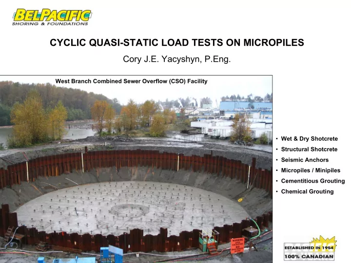
West Branch Combined Sewer Overflow (CSO) Facility
- Wet & Dry Shotcrete
- Structural Shotcrete
- Seismic Anchors
- Micropiles / Minipiles
- Cementitious Grouting
- Chemical Grouting
SLIDE 2
- Recently, 212 GEWI-Piles were installed in
New Westminster, BC, to support a 20,000 m3 partially submerged buried storage tank subject to cyclic loading.
- Following, two pre-production full scale
verification cyclic load tests are reviewed
- “Cyclic” loading, as described in this
paper, refers to quasi-static alternating compression and tensile loads, with no dynamic component. Details of this type of pile response are provided.
- The GEWI-Piles were installed by a local
specialty foundation contractor, Southwest Contracting Ltd.
CSO Facility INTRODUCTION
SLIDE 3
CSO Facility
Figure 2a. GEWI-Pile Layout Plan
DESIGN
SLIDE 4
CSO Facility
Figure 2b. Tank Section
DESIGN
SLIDE 5 DESIGN CSO Facility
- The tank structure required
foundations to resist uplift forces due to buoyancy caused by groundwater table rise and compression forces caused by filling of the tank. Cyclic loading per GEWI-Pile:
- Max. factored tension load = 380 kN
- Max. working tension load = 200 kN
- Max. working compression load
(including 12 mm creep effect) = 600 kN
- Max. working compression load (no
creep effect) = 140 kN “Heel”
- The Engineers designed the “heel”
to resist uplift forces due to buoyancy along the perimeter of the tank so no cyclic effects.
- Long term creep in the soils near the
centre of the tank was anticipated to be, as much as, 12 mm.
SLIDE 6
CSO Facility DESIGN
Figure 3. Micropile Shop Drawing
SLIDE 7
CSO Facility GENERALIZED SOIL PROFILE
interbedded SILT or CLAY and SAND > 2 m Unit c medium dense to dense SAND 12 to 15 m Unit b2 loose to medium dense sand 2 to 2.5 m Unit b1 soft to firm sandy SILT - FILL? 4 to 5 m Unit a2 silty sand, sandy silt – FILL 0 to 1.5 m Unit a1 Description Thickness Soil Unit
(Uthayakumar and Macleod 2004) Table 1. Generalized Soil Profile Figure 1. CPT04-3 Log
SLIDE 8 CSO Facility DRILLING
Drill string advancement Due to the sandy soils and high groundwater table, a cased direct circulation drill system was specified with the objective to minimize disturbance at the soil-grout interface and ground loss.
- Disposed cuttings shall not exceed 110% of
the theoretical drill hole volume.
- Casing shall not have an O.D. < 133 mm
- The use of air drilling is not permitted
- Drilling using augers is not permitted
SLIDE 9 CSO Facility DRILLING
- Drilling was performed inside a full cut-off wall, extending to a silt/clay layer at -22 m elevation located
at the crest of a sloped excavation.
- The drill hole was advanced from -6.8 m elevation during on-going dewatering activities.
- Diesel/hydraulic rig utilizing double head duplex overburden drilling method advanced a 133 Ø
temporary casing.
SLIDE 10 CSO Facility DRILLING
- Medium class hydraulic crawler drill rig
- Rotary-Rotary drill head configuration
- Water flush with potable water
- As-drilled hole diameter = 152 mm
SLIDE 11 CSO Facility INSTALLATION
- Full length GEWI-Piles were installed using a zoom boom type machine
- No couplers used since GEWI-Piles ordered full-length from the factory.
- GEWI-Piles installed immediately after drilling then tremie grouted
SLIDE 12 CSO Facility GROUTING
A high early strength, thixotropic, cement grout
- Water : Cement Ratio < 0.35 was specified
- Primary grouting to 517 kPa minimum
- Pressure grouting thru the top of the
casing at intervals as the casing was being pulled.
- One stage of post-grouting to 5,170 kPa
minimum was performed prior to any testing.
- A subsequent test program, on-site,
showed post-grouting had little influence on test results.
SLIDE 13 CSO Facility CYCLIC LOAD TEST ARRANGEMENT
- Reaction I-Beam repeatedly tilted during
tension loading and translated laterally due to slight off-centered loading.
- Further alterations to the initial framework were
ruled out. Consequently the jacking arrangement was modified.
- During each load reversal the top nuts of each
reaction pile and test pile were loosened and tightened, respectively, in order to change loading direction. Test setup 1
SLIDE 14
CSO Facility CYCLIC LOAD TEST ARRANGEMENT
Test setup 1
SLIDE 15 CSO Facility CYCLIC LOAD TEST ARRANGEMENT
- Added test beams overtop the original test
setup
- Test setup did not meet ASTM standards with
respect to spacing of the reaction piles and test
- pile. No standard was specified during tendering.
- Recommend future test setups meet ASTM
standard D3689 for tension tests and ASTM D1143-81 for compression tests. Test setup 2
SLIDE 16
CSO Facility CYCLIC LOAD TEST ARRANGEMENT
Test setup 2 Two 590 kN tension jacks synchronized by hydraulically connecting each to the same hydraulic power pack. 1,470 kN compression jack
SLIDE 17
CSO Facility CYCLIC PERFORMANCE TEST PROCEDURE
Four performance verification tests in total were performed on each test GEWI-Pile in the following sequence: 1. A 250 kN tension test in accordance with PTI-1996. 2. A 175 kN compression test in accordance with PTI-1996 3. A cyclic test starting from a 250 kN tension alignment load to 600 kN compression load by increasing compression loading 75 kN each successive cycle. 4. A 450 kN tension test in accordance with PTI-1996 Grout Collar isolated from the pile
SLIDE 18
CSO Facility PERFORMANCE & EXTENDED CREEP TEST RESULTS
SLIDE 19
CSO Facility PERFORMANCE & EXTENDED CREEP TEST RESULTS
SLIDE 20
CSO Facility PERFORMANCE & EXTENDED CREEP TEST RESULTS
The shape of cycle 7 shows similar unloading stress histories and shows departure from a linear, reproducible cyclic loading pattern.
SLIDE 21
CSO Facility PERFORMANCE & EXTENDED CREEP TEST RESULTS
SLIDE 22
CSO Facility PERFORMANCE & EXTENDED CREEP TEST RESULTS
SLIDE 23
CSO Facility PERFORMANCE & EXTENDED CREEP TEST RESULTS
Log-linear increasing displacement to – 0.71 mm during the final two log cycle Non-log-linear displacement to – 0.61 mm during the final two log cycle
SLIDE 24
CSO Facility CONCLUSIONS & FINAL REMARKS
Recommendations 1. Use of strain gauges in future tests to determine shape of the load distribution along the fixed anchor and its behavior under cyclic loading 2. Repeated cyclic loading at design load to determine how the number of load cycles affects load holding capacity. Based on the test results of the two verification cyclic load tests, the installed GEWI-Piles were considered adequate to sustain their design loads