
SLIDE 1
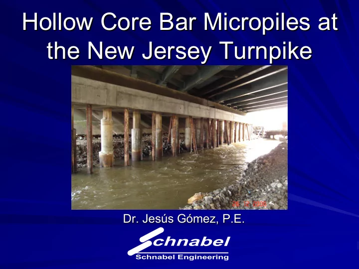
Hollow Core Bar Micropiles at Hollow Core Bar Micropiles at the New Jersey Turnpike the New Jersey Turnpike
- Dr. Jesús Gómez, P.E.
- Dr. Jesús Gómez, P.E.
Hollow Core Bar Micropiles at Hollow Core Bar Micropiles at the New - - PowerPoint PPT Presentation
Hollow Core Bar Micropiles at Hollow Core Bar Micropiles at the New Jersey Turnpike the New Jersey Turnpike Dr. Jess Gmez, P.E. Dr. Jess Gmez, P.E. Outline Outline Project Overview Project Overview Micropile Characteristics
Bridge 0.42L Bridge 7.85
Bridge 0.42L Bridge 7.85
Bridge 0.42L Bridge 7.85
P3 P2 P1
P2 P1
Bridge 0.42L Minimum Cased Length 35 ft Minimum Cased Length 35 ft Minimum Bond Length 30 ft Minimum Bond Length 30 ft Nominal Grout Body Diameter 6 in Nominal Grout Body Diameter 6 in
Bridge 7.85 Minimum Cased Length 45 ft Minimum Cased Length 45 ft Minimum Bond Length 40 ft Minimum Bond Length 40 ft Nominal Grout Body Diameter 9 in Nominal Grout Body Diameter 9 in
Grout Mix
Drilling grout, 10 gallons water per 1 bag of cement
Final grout, 5 gallons water per 1 bag of cement
Drilling advance rate Drilling advance rate Grout pressure Grout pressure Total micropile depths Total micropile depths
1.45 to 1.60 for drilling grout 1.45 to 1.60 for drilling grout Minimum 1.8 for final grout Minimum 1.8 for final grout
Micropiles in medium dense sand (Bridge 0.42L) : Load Transfer Ratio = 10 kip/ft (Bond Strength = 44 Load Transfer Ratio = 10 kip/ft (Bond Strength = 44 psi psi) )
Micropiles in stiff silty clay (Bridge 7.85): Load Transfer Ratio = 4.1 kip/ft (Bond Strength = 18 Load Transfer Ratio = 4.1 kip/ft (Bond Strength = 18 psi psi) )
0.0 0.1 0.2 0.3 10 20 30 40 50 60 70 80 90 100 110 120 Load (kip) Deflection (in)
0.0 0.1 0.2 0.3 0.4 0.5 20 40 60 80 100 120 Load (kip) Deflection (in)
Axial Load
b b be be
be b
L P a =
Pb ∆Pb δbe
5 10 15 20 25 30 4 6 8 10 12 14 16 18 20 More Load Transfer Ratio (kip/ft) Number of Micropiles
2 4 6 8 10 12 14 2 4 6 8 10 12 14 16 18 20 Load Transfer Ratio (kip/ft) Number of Micropiles
10 – 28 psi 9 - 27 psi Stiff Silty Clay 10 – 28 psi 27 – 53 psi Medium Dense Sand Bond Strength Suggested By FHWA Type B micropile Mobilized Bond Strength in Proof Tests Soil Type