Common Coordinate Viewing in 3D Systems (Chapt. 6 in FVD, Chapt. - - PDF document

common coordinate viewing in 3d systems
SMART_READER_LITE
LIVE PREVIEW

Common Coordinate Viewing in 3D Systems (Chapt. 6 in FVD, Chapt. - - PDF document

Common Coordinate Viewing in 3D Systems (Chapt. 6 in FVD, Chapt. 12 in Hearn & Baker) Object space local to each object World space common to all objects Eye space / Camera space derived from view frustum


slide-1
SLIDE 1

Viewing in 3D

(Chapt. 6 in FVD, Chapt. 12 in Hearn & Baker)

Common Coordinate Systems

  • Object space

– local to each object

  • World space

– common to all objects

  • Eye space / Camera

space

– derived from view frustum

  • Screen space

– indexed according to hardware attributes

Specifying the Viewing Coordinates

  • Viewing Coordinates system, [u,

v, w], describes 3D objects with respect to a viewer.

  • A viewing plane (projection

plane) is set up perpendicular to w and aligned with (u,v).

  • To set a view plane we have to

specify a view-plane normal vector, N, and a view-up vector, Up, (both, in world coordinates):

x z y

P P0

Up u v w

View plane

  • P0=(x0,y0,z0) is a point where a

camera is located.

  • P is a point to look-at.
  • N=(P0-P)/|P0-P| is the view-plane

normal vector.

  • Up is the view up vector, whose

projection onto the view-plane is directed up.
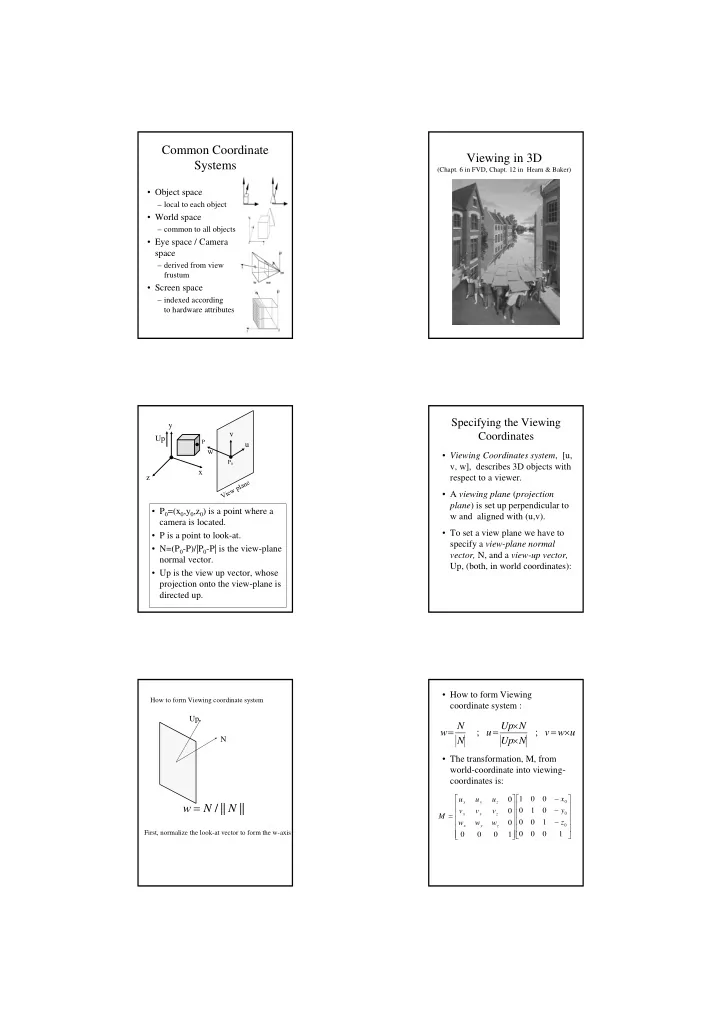
  • How to form Viewing

coordinate system :

  • The transformation, M, from

world-coordinate into viewing- coordinates is:

u w v N Up N Up u N N w

  • ;

;

  • 1

1 1 1 1 z y x w w w v v v u u u M

z y x z y x z y x

How to form Viewing coordinate system

|| || / N N w

Up N

First, normalize the look-at vector to form the w-axis

slide-2
SLIDE 2

Create U perpendicular to Up and W

| | W Up W Up U

  • Up

W U

Create V perpendicular to U and W

Up W U V

U W V

  • Projections
  • Viewing 3D objects on a 2D display

requires a mapping from 3D to 2D.

  • A projection is formed by the

intersection of certain lines (projectors) with the view plane.

  • Projectors are lines from the center
  • f projection through each point in

the object.

Center of Projection

  • Center of projection at infinity

results with a parallel projection.

  • A finite center of projection results

with a perspective projection.

Parallel Projection

A parallel projection preserves relative proportions of objects, but does not give realistic appearance (commonly used in engineering drawing).

slide-3
SLIDE 3

Perspective Projection

A perspective projection produces realistic appearance, but does not preserve relative proportions.

Parallel Projection

  • Projectors are all parallel.
  • Orthographic: Projectors are

perpendicular to the projection plane.

  • Oblique: Projectors are not

necessarily perpendicular to the projection plane.

Orthographic Oblique

  • Since the viewing plane is aligned

with (xv,yv), orthographic projection is performed by:

Orthographic Projection

  • 1

1 1 1 1 1

v v v v v p p

z y x y x y x

P0

xv yv zv

(x,y,z) (x,y)

  • Lengths and angles of faces

parallel to the viewing planes are preserved.

  • Problem: 3D nature of projected
  • bjects is difficult to deduce.

Front view Top View Side View

Oblique Projection

  • Projectors are not perpendicular to the

viewing plane.

  • Angles and lengths are preserved for faces

parallel to the plane of projection.

  • Somewhat preserves 3D nature of an object.
  • Cavalinear projection :

– Preserves lengths of lines perpendicular to the viewing plane. – 3D nature can be captured but shape seems distorted.

  • Cabinet projection:

– lines perpendicular to the viewing plane project at 1/2 of their length. – A more realistic view than the Cavalinear projection.

45° 1 1 1 x z y x z 45° 1/2 1 1

Cabinet Projection Cavalinear Projection

slide-4
SLIDE 4

Perspective Projection

  • In a perspective projection, the center
  • f projection is at a finite distance from

the viewing plane.

  • Parallel lines that are not parallel to the

viewing plane, converge to a vanishing point. – A vanishing point is the projection of a point at infinity.

Z-axis vanishing point y x z

Vanishing Points

  • There are infinitely many general

vanishing points.

  • There can be up to three axis

vanishing points (principal vanishing points).

  • Perspective projections are

categorized by the number of principal vanishing points, equal to the number of principal axes intersected by the viewing plane.

  • Most commonly used: one-point

and two-points perspective.

x y z

One point (z axis) perspective projection Two points perspective projection

z axis vanishing point. x axis vanishing point.

slide-5
SLIDE 5

3-point Perspective

M.C.Escher’ s "Relativity" where 3 worlds co- exist thanks to 3-point perspective.

3-point Perspective Perspective Projection

A perspective projection produces realistic appearance, but does not preserve relative proportions.

  • Using similar triangles it follows:

x y z

(x,y,z)

(xp,yp,0)

center of projection

d d x z

(x,y,z)

xp

d z y d y d z x d x

p p

  • ;

; ;

  • p

p p

z d z y d y d z x d x

slide-6
SLIDE 6
  • Thus, a perspective projection

matrix is defined:

  • 1

1 1 1 d M per

  • d

d z y x z y x d P M per 1 1 1 1 1

; ;

  • p

p p

z d z y d y d z x d x

Observations

  • Mper is singular (|Mper|=0), thus

Mper is a many to one mapping

  • Points on the viewing plane

(z=0) do not change.

  • The vanishing point of parallel

lines directed to (Ux,Uy,Uz) is at [dUx/Uz, dUy/Uz].

  • When d , Mper

Mort

Zoom-in

Center of Projection Projection plane

Zoom-in

Center of Projection Projection plane

What is the difference between moving the center of projection and moving the projection plane?

Center of Projection z Projection plane Center of Projection z Projection plane Center of Projection z Projection plane

Original Moving the Center of Projection Moving the Projection Plane

Summary

Planar geometric projections

Parallel Perspective Orthographic Oblique Cavalinear Cabinet Other Top Front Side Other Two point One point Three point

slide-7
SLIDE 7

Another view in Perspective Another view in Perspective

7KUHHSRLQWSHUVSHFWLYH 7ZRSRLQWSHUVSHFWLYH 7KUHHSRLQWSHUVSHFWLYH )RXUSRLQWSHUVSHFWLYH )LYHSRLQWSHUVSHFWLYH" 6L[SRLQWSHUVSHFWLYH"

Fisheye views of the Hagia Sophia (Istanbul) (also known as Aya Sofya )

slide-8
SLIDE 8

Fisheye view Vertical lines House of Stairs

M.C. Escher’ s House of Stairs

View Window

  • After objects were projected onto the

viewing plane, an image is taken from a View Window.

  • A view window can be placed

anywhere on the view plane.

  • In general the view window is aligned

with the viewing coordinates and is defined by its extreme points: (xwmin,ywmin) and (xwmax,ywmax)

yv xv zv V i e w p l a n e View window

(xwmin,ywmin) (xwmax,ywmax)

View Volume

  • Given the specification of the view

window, we can set up a View Volume.

  • Only objects inside the view volume

might appear in the display, the rest are clipped.

  • In order to limit the infinite view volume we

define two additional planes: Near Plane and Far Plane.

  • Only objects in the bounded view volume

can appear.

  • The near and far planes are parallel to the

view plane and specified by znear and zfar.

  • A limited view volume is defined:

– For orthographic: a rectangular parallelpiped. – For oblique: an oblique parallelpiped. – For perspective: a frustum. zv

Near Plane Far Plane w i n d

  • w

w i n d

  • w

zv

Near Plane Far Plane

slide-9
SLIDE 9

Canonical View Volumes

  • In order to determine the objects that

are seen in the view window we have to clip objects against six planes forming the view volume.

  • Clipping against arbitrary 3D plane

requires considerable computations.

  • For fast clipping we transform the

general view volume to a canonical view volume against which clipping is easy to apply.

Viewing Coordinates Projection Transformation Canonical view Transformation Clipping

Trivial Accept/Reject

Red polygons are rejected Black are accepted And Blue are tagged for clipping

Classify the vertices of the polygons against each side Si of the frustum in turn: If all the vertices are on the outside of some Si, then cull the polygon, otherwise, Polygons with all its vertices inside all Sj are accepted. All others are tagged. z z

Affine Transformation:

n n

  • C

By Ax y x

z z

1

  • 1
  • 1

1

Perspective transformation:

  • c

c c

  • c

c c c c c 1 1 2 1 1 1

c c c c c c

z y x n f fn n f n f z y x

  • 1

z x x z x x c

  • c

c c

  • c
  • c

c c 1 z y y z y y c

  • c

c c

  • c
  • c

c c 1

  • 1

1 1

  • n
  • 1

1 1

  • f

OpenGL Transformation Pipe-Line

Homogeneous coordinates in World System ModelView Matrix Projection Matrix Clipping Viewport Transformation Viewing Coordinates Clip Coordinates Window Coordinates

slide-10
SLIDE 10