viewing outline
play

VIEWING OUTLINE Positioning a Camera Projections Orthogonal - PowerPoint PPT Presentation

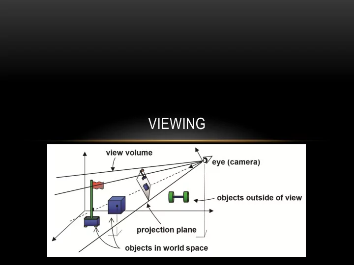
VIEWING OUTLINE Positioning a Camera Projections Orthogonal Perspective COMPUTER VIEWING There are three aspects of the viewing process, all of which are implemented in the pipeline, Positioning the camera


  1. VIEWING

  2. OUTLINE • Positioning a Camera Projections • • Orthogonal Perspective •

  3. COMPUTER VIEWING • There are three aspects of the viewing process, all of which are implemented in the pipeline, • Positioning the camera • Setting the model-view matrix • Selecting a lens • Setting the projection matrix • Clipping • Setting the view volume 3

  4. THE OPENGL CAMERA • In OpenGL, initially the object and camera frames are the same • Default model-view matrix is an identity • The camera is located at origin and points in the negative z direction • OpenGL also specifies a default view volume that is a cube with sides of length 2 centered at the origin • Default projection matrix is an identity 4

  5. MOVING THE CAMERA FRAME • If we want to visualize object with both positive and negative z values we can either • Move the camera in the positive z direction • Translate the camera frame • Move the objects in the negative z direction • Translate the world frame • Both of these views are equivalent and are determined by the model-view matrix Want a translation ( Translate(0.0,0.0,-d); ) • • d > 0 5

  6. MOVING CAMERA BACK FROM ORIGIN frames after translation by – d default frames d > 0 6

  7. A LOOKAT FUNCTION • Given: • the location of the camera/eye (a point) • the location of the target to look at (a point) • a suitable “up” direction in the world space, usually y axis (a vector) • Create the transformation matrix to “move” the camera/world so it reflects this configuration 7

  8. CAMERA COORDINATE SYSTEM

  9. THE LOOKAT MATRIX

  10. A LOOKAT METHOD IN JAVA/JOGL (1/2) private Matrix 3D lookAt(Point3D eye, Point3D target, Vector 3D y) { Vector3d eyeV = new Vector3D(eye); Vector3D targetV = new Vector3D(target); Vector3d fwd = (targetV.minus(eyeV).normalize(); Vector3D side = (fwd.cross(y).normalize(); Vector3d up = (side.cross(fwd).normalize(); …

  11. A LOOKAT METHOD IN JAVA/JOGL (2/2) … Matrix3D look = new Matrix3D(); look.setElementAt(0, 0, side.getX()); look.setElementAt(1, 0, up.getX); look.setElementAt(2, 0, -fwd.getX()); look.setElementAt(3, 0, 0.0f); look.setElementAt(0, 1, side.getY()); look.setElementAt(1, 1, up.getY()); look.setElementAt(2, 1, -fwd.getY()); look.setElementAt(3, 1, 0.0f); look.setElementAt(0, 2, side.getZ()); look.setElementAt(1, 2, up.getZ()); look.setElementAt(2, 2, -fwd.getZ()); look.setElementAt(3, 2, 0.0f); look.setElementAt(0, 3, side.dot(eyeV.mult(-1))); look.setElementAt(1, 3, up.dot(eyeV.mult(-1))); look.setElementAt(2, 3, (fwd.mult(-1).dot(eveV.mult(-1))); look.setElementAt(3, 3, 1.0f); return(look); }

  12. CLASSICAL PROJECTIONS 12

  13. PLANAR GEOMETRIC PROJECTIONS • Standard projections project onto a plane Projectors are lines that either • • converge at a center of projection are parallel • • Such projections preserve lines but not necessarily angles • • Nonplanar projections are needed for applications such as map construction 13

  14. MAIN CLASSES OF PLANAR GEOMETRICAL PROJECTIONS • Perspective: determined by Center of Projection (COP) (in our diagrams, the “eye”) – More natural, simulates what our eyes or a camera sees Parallel: determined by Direction of Projection (DOP) (projectors are parallel — do not converge • to “eye” or COP). – Used in engineering and architecture for measurement purposes • In general, a projection is determined by where you place the projection plane relative to principal axes of object (relative angle and position), and what angle the projectors make with the projection plane 14

  15. TAXONOMY OF PLANAR GEOMETRIC PROJECTIONS planar geometric projections parallel perspective 1 point 2 point 3 point multiview axonometric oblique orthographic isometric dimetric trimetric 1 5

  16. ORTHOGONAL VIEWING near and far measured from camera 16

  17. EARLY FORMS OF PROJECTION • Ancient Egyptian Art: – Multiple Viewpoints – Parallel Projection – Tomb of Nefertari, Thebes (19th Dyn, ~1270 BC), Queen led by Isis. Mural • Note how the depiction of the body implies a front view but the feet and head imply side view (early cubism) 17

  18. PERSPECTIVE 18

  19. EARLY ATTEMPTS AT PERSPECTIVE • In art, an attempt to represent 3D space more realistically • Earlier works invoke a sense of 3D space but not systematically • Lines converge, but no single vanishing point Giotto Franciscan Rule Approved Assisi, Upper Basilica c.1295-1300 19

  20. MORE REALISTIC PERSPECTIVE

  21. ORTHOGRAPHIC PROJECTION Projectors are orthogonal to projection surface 21

  22. MULTIVIEW ORTHOGRAPHIC (PARALLEL) • Used for: engineering drawings of machines, – machine parts working architectural drawings – Pros: • accurate measurement possible – – all views are at same scale Cons: • – does not provide “realistic” view or sense of 3D form Usually need multiple views to get a • three-dimensional feeling for object 22

  23. ADVANTAGES AND DISADVANTAGES • Preserves both distances and angles Shapes preserved • • Can be used for measurements • Building plans • Manuals Cannot see what object really looks like because many surfaces hidden from view • • Often we add the isometric 23

  24. AXONOMETRIC PROJECTIONS Allow projection plane to move relative to object classify by how many angles of a corner of a projected cube are the same q 1 q 2 q 3 none: trimetric two: dimetric three: isometric 24

  25. TYPES OF AXONOMETRIC PROJECTIONS 25

  26. AXONOMETRIC (PARALLEL) • Same method as multiview orthographic projections, except projection plane not parallel to any of coordinate planes ; parallel lines equally foreshortened • Isometric : Angles between all three principal axes equal (120º). Same scale ratio applies along each axis • Dimetric: Angles between two of the principal axes equal; need two scale ratios • Trimetric: Angles different between three principal axes; need three scale ratios 26

  27. ISOMETRIC PROJECTION Used for: • • catalogue illustrations • patent office records • furniture design structural design • 3d Modeling in real time • Construction of an isometric projection: • Pros: projection plane cuts each principal axis by 45 ° don’t need multiple views • illustrates 3D nature of object • measurements can be made to scale along • principal axes Cons: • lack of foreshortening creates distorted • appearance • more useful for rectangular than curved shapes 27

  28. A DESK IN PARALLEL multiview orthographic cabinet cavalier 28

  29. LACK OF FORESHORTENING

  30. AXONOMETRIC PROJECTION IN GAMES Video games have been using • isometric projection for ages. It all started in 1982 with Q*Bert and • Zaxxon which were made possible by advances in raster graphics hardware • Still in use today when you want to see things in distance as well as things close up (e.g. strategy, simulation games) • SimCity • StarCraft 30

  31. ORTHOGONAL MATRIX • Two steps Move center to origin • T(-(left+right)/2, -(bottom+top)/2,(near+far)/2)) Scale to have sides of length 2 • S(2/(left-right),2/(top-bottom),2/(near-far))    2 right left  0 0     right left right left    2 top bottom    0 0     top bottom top bottom P = ST =    2 far near   0 0     near far far near     0 0 0 1 31

  32. ORTHOGRAPHIC PROJECTION MATRIX

  33. PERSPECTIVE PROJECTION Projectors coverge at center of projection 33

  34. PERSPECTIVE PROJECTIONS • Used for: • fine art • Human visual system… • Pros: • gives a realistic view and feeling for 3D form of object • Cons: • does not preserve shape of object or scale (except where object intersects projection plane) • Different from a parallel projection because parallel lines not parallel to the projection plane • converge size of object is diminished with distance • foreshortening is not uniform • If we were viewing this scene using parallel Two understandings: Vanishing Point and View Point • projection, the tracks would not converge 34

  35. VANISHING POINTS • Parallel lines (not parallel to the projection plan) on the object converge at a single point in the projection (the vanishing point ) • Drawing simple perspectives by hand uses these vanishing point(s) vanishing point 35

  36. VANISHING POINTS Lines extending from edges converge to common vanishing point(s) • • For right-angled forms whose face normals are perpendicular to the x, y, z coordinate axes, number of vanishing points = number of principal coordinate axes intersected by projection plane z One Point Perspective ( z -axis vanishing point) Two Point Perspective ( z , and x -axis vanishing points) Three Point Perspective ( z , x , and y -axis vanishing points) 36

  37. THREE-POINT PERSPECTIVE • No principal face parallel to projection plane • Three vanishing points for cube 37

  38. TWO-POINT PERSPECTIVE • One principal direction parallel to projection plane • Two vanishing points for cube 38

  39. ONE-POINT PERSPECTIVE • One principal face parallel to projection plane • One vanishing point for cube 39

Download Presentation
Download Policy: The content available on the website is offered to you 'AS IS' for your personal information and use only. It cannot be commercialized, licensed, or distributed on other websites without prior consent from the author. To download a presentation, simply click this link. If you encounter any difficulties during the download process, it's possible that the publisher has removed the file from their server.

Recommend


More recommend