6/23/2015 Development and Optimisation of the Panther engine - - PDF document

6 23 2015
SMART_READER_LITE
LIVE PREVIEW

6/23/2015 Development and Optimisation of the Panther engine - - PDF document

6/23/2015 Development and Optimisation of the Panther engine primary drive system 30 th June 2015 Jarek Rosinski, Steve Lowry, Pranav Kalke, Tomas Rosinski, David Smurthwaite (Transmission Dynamics) and Kevin Maile (Ford Motor Company)


slide-1
SLIDE 1

6/23/2015 1

Development and Optimisation of the Panther engine primary drive system

30th June 2015 Jarek Rosinski, Steve Lowry, Pranav Kalke, Tomas Rosinski, David Smurthwaite (Transmission Dynamics) and Kevin Maile (Ford Motor Company)

Introduction

2

Extensive development work was undertaken as part of the Panther diesel engine programme and the subjects reported in this paper cover:

  • Measurement of dynamic torque in the primary drive

gears, to verify simulation predictions,

  • Optimisation of primary drive system gear

microgeometry to reduce tonal whine,

  • Development of a test rig capable of performing

accelerated life testing and to verify safety factors.

30th June 2015

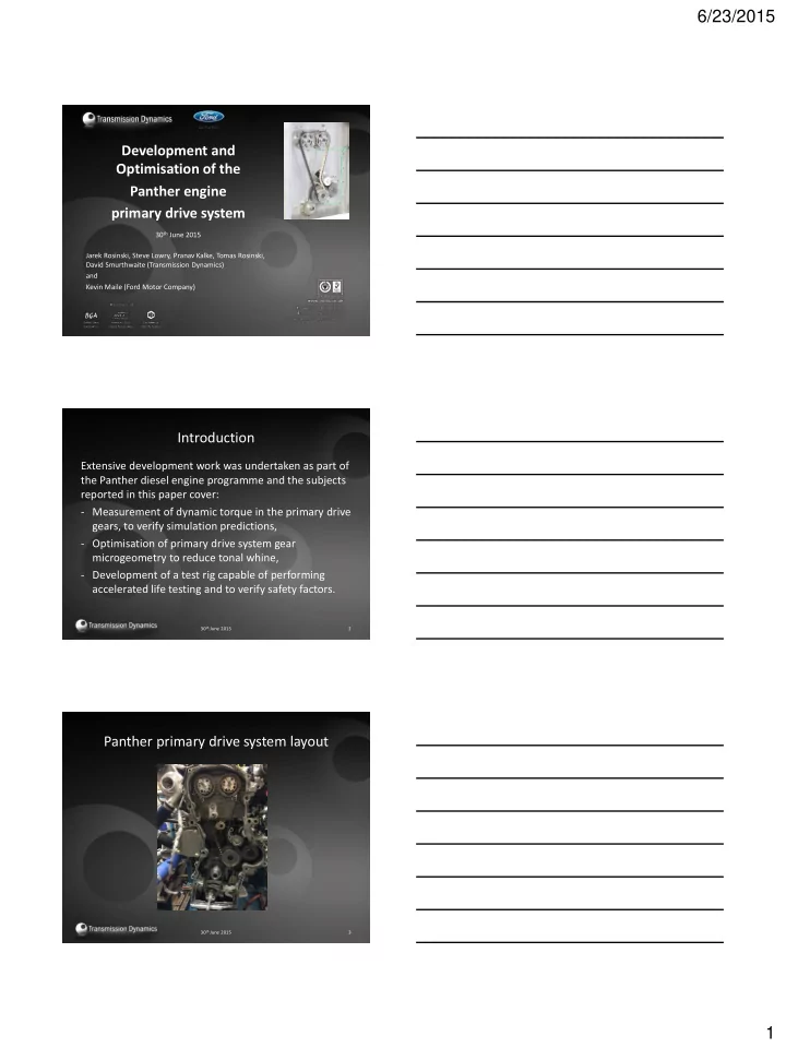
Panther primary drive system layout

30th June 2015 3

slide-2
SLIDE 2

6/23/2015 2

Gear dynamic torque

30th June 2015 4

Conversion of standard gears to calibrated load cells

Gear dynamic torque measurements

30th June 2015 5

Load measuring gears installed in the engine

Gear dynamic torque measurements

30th June 2015 6

Amplified signals are extracted via sliprings

slide-3
SLIDE 3

6/23/2015 3

30th June 2015 7

Simulated torque Measured torque

FIP gear, 100% load, 4,440 rpm, Sampling frequency, fs = 44.1 kHz.

Dynamic Torque Results

Timing belt load measurements

30th June 2015 8

Conversion from the rotating frame of reference

30th June 2015 9

slide-4
SLIDE 4

6/23/2015 4

Format of typical belt load result

30th June 2015 10

Optimisation of gear microgeometry

30th June 2015 11

A range of microgeometry correction parameters in various combinations were evaluated to

  • ptimise Transmission

Error (TE) for each mesh, in order to minimise gear whine.

Gear microgeometry parameters

30th June 2015 12

  • Profile tip relief (magnitude and extent),
  • Lead crowning,
  • Lead end relief.

These were applied and TE evaluated for a range

  • f load conditions and mesh misalignments.
slide-5
SLIDE 5

6/23/2015 5

Example of gear inspection report

30th June 2015 13

Optimisation of gear microgeometry

30th June 2015 14

Example: Effect on TE of ‘long’ tip relief with 6µm crowning for a range of loads.

Tip Chamfer (0.3mm x 45º)

With chamfer Without chamfer

30th June 2015 15

slide-6
SLIDE 6

6/23/2015 6

30th June 2015 16 30th June 2015 17

Optimisation of gear microgeometry

30th June 2015 18

Effect on TE

slide-7
SLIDE 7

6/23/2015 7

30th June 2015 19

Effect on tonal noise

Durability testing of primary drive system gears

30th June 2015 20

Overloading the gears on the running engine is not possible !

Layout of the test rig

30th June 2015 21

High frequency torsional overload application

slide-8
SLIDE 8

6/23/2015 8

Dynamic Torsional Exciter

30th June 2015 22

Neodymium supermagnets generate two torsional pulses per revolution.

Engine speed 30th June 2015 23

Test Rig Control

PC controlled using NI Virtual Interface

30th June 2015 24

slide-9
SLIDE 9

6/23/2015 9

Examples of gears after testing

These gears completed 2,290 hours of accelerated durability testing, and are still in good condition (light wear) yielding minimum safety factor of 1.4

30th June 2015 25

Conclusions

  • Dynamic torque transmitted by the primary drive

gears in a running engine was evaluated using novel instrumentation techniques.

  • This enabled the optimisation of gear microgeometry

to deliver acceptable NVH performance.

  • Accelerated durability testing was possible using a

unique component test rig capable of imparting high frequency, high dynamic torque loads to the primary drive system.

30th June 2015 26

Thank you for your attention

Questions?

30th June 2015 27