
9/7/2010 1 Remote Sensing Technologies for Detecting Bridge Deterioration and Condition Assessment Tess Ahlborn, Ph.D., P.E.
with Devin Harris, Colin Brooks, Arthur Endsley, Darrin Evans, Renee Oats, Khatereh Vaghefi, Larry Sutter, Bob Shuchman, Joe Burns, and Chris Roussi
Mi hi T h l i l U i it Mi hi T h l i l U i it Michigan Technological University Michigan Technological University
August 18, 2010 NDT/NDE for Highway Bridges – SMT 2010
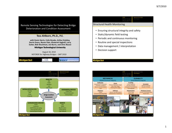
Structural Health Monitoring
- Ensuring structural integrity and safety
SHM Project Concept Remote Sensing In-Progress General Concepts Techniques
g g y y
- Static/dynamic field testing
- Periodic and continuous monitoring
- Routine and special inspections
- Data management / interpretation
Data management / interpretation
- Decision support
2
BRIDGE TYPE ‐Slab ‐Girder ‐Box‐Beam Arch
SHM Project Concept Remote Sensing In-Progress General Concepts Techniques
ENVIRONMENTAL CONDITIONS ‐Freeze‐Thaw ‐Environmental Loads ‐Chemical Attack ‐Arch ‐Cable‐Stayed MATERIAL (SUPERSTRUCTURE) ‐Concrete ‐Steel ‐Timber ‐Composite
Bridge Condition Assessment
3
LOADING/BOUNDARY CONDITIONS ‐Simple ‐Continuous ‐AASHTO Notional Loading ‐State Specified Loading ‐Overloads/Special Loading GEOMETRY ‐Span ‐Width ‐Skew/Curvature ‐Girder Spacing ‐Deck Thickness Cracking ‐ Visual Inspection ‐Acoustic Emission Corrosion ‐ Half‐cell Potential
DURABILITY
(Local Material Integrity)
Strain
‐Electrical Resistance Gages Fib O ti G
Deflection
‐Displacement Transducers ‐‐ Tiltmeters (rotation)
MECHANICAL
(Global Structural Integrity)
SHM Project Concept Remote Sensing In-Progress General Concepts Techniques ‐ Ultrasonic Pulse Velocity ‐ Thermography
Thickness (Cover)
‐ Ground Penetrating Radar ‐ Impact Echo
Delamination
‐ Chain Drag ‐ Imact Echo ‐ Acoustic Emission ‐Fiber‐Optic Gages ‐ Vibrating Wire Gages
Stiffness
‐ Seismic (accelerometers) ‐ Displacement Transducers
Thickness
‐ Caliper ‐ Ground Penetrating Radar ( ) ‐ Seismic (accelerometers) ‐ Laser
4