
11/05/2016 1
Component-Based Software Design – LMES
1
Scheduling tasks on Reconfigurable FPGA architectures
Mauro Marinoni
ReTiS Lab, TeCIP Institute Scuola superiore Sant’Anna - Pisa
Component-Based Software Design – LMES
2
Agenda
The topics that will be addressed are:
- Overview on basic characteristics of the FPGA;
- FPGA reconfiguration capabilities;
- Timing analysis for reconfigurable FPGA platforms;
- Kernel
mechanisms to support reconfigurable systems.
Component-Based Software Design – LMES
3
FPGA
Overview
Component-Based Software Design – LMES
4
Definition
A field-programmable gate array (FPGA) is an integrated circuit designed to be configured by a customer or a designer after manufacturing – hence "field-programmable". The FPGA configuration is generally specified using a hardware description language (HDL).
Component-Based Software Design – LMES
5
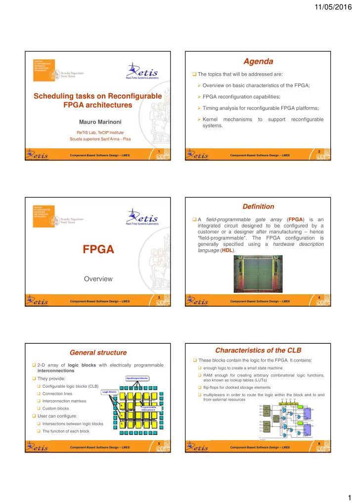
General structure
2-D array of logic blocks with electrically programmable interconnections They provide:
Configurable logic blocks (CLB) Connection lines Interconnection matrixes Custom blocks
User can configure:
Intersections between logic blocks The function of each block
Component-Based Software Design – LMES
6
Characteristics of the CLB
These blocks contain the logic for the FPGA. It contains:
enough logic to create a small state machine RAM enough for creating arbitrary combinatorial logic functions, also known as lookup tables (LUTs) flip-flops for clocked storage elements multiplexers in order to route the logic within the block and to and from external resources