
SLIDE 1
Rachele Floeser Project Manager Alex Langkamp Project Manager Sabrina Caliri Facilitator/Engineer Nick Accuosti Engineer Matt DePalo Engineer Mike Everett Engineer
Workstation Redesign Detailed Design Rachele Floeser Project - - PowerPoint PPT Presentation
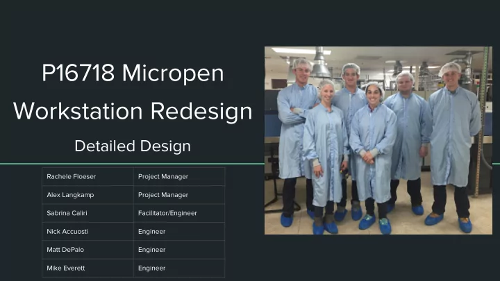
P16718 Micropen Workstation Redesign Detailed Design Rachele Floeser Project Manager Alex Langkamp Project Manager Sabrina Caliri Facilitator/Engineer Nick Accuosti Engineer Matt DePalo Engineer Mike Everett Engineer Review and Updates
Rachele Floeser Project Manager Alex Langkamp Project Manager Sabrina Caliri Facilitator/Engineer Nick Accuosti Engineer Matt DePalo Engineer Mike Everett Engineer
Review and Updates Operator Feedback Test Plan Design Models Project Management
ergonomic risk factors for the operator
Issue The viewing apparatus solution of using a screen potentially causes different ergonomic challenges for the
Action Taken Performed initial testing using the DinoXcope at the Micropen workstation. Identified some software and hardware requirements of the viewing apparatus solution Current Situation Continuing to identify requirements and additional testing methods for the subsystem Issue Tooling solutions used for the touch-up procedure creates more challenges for the operator, outside of the known challenges Action Taken Researched precise tooling operations. Sketched ideas and created solidworks documents of potential solutions Current Situation Developed multiple solutions that vary in difficulty to implement and also in simplicity of the operation for the
Requirement # Rank Function Metric Unit Marginal Value Ideal Value S36 9 Testing
All measured stresses are within a FOS for the given part geometry
FOS 3 >5 S37 9 Testing
All tests do not fail within avg. hourly
cycles/ hour 50 >60
○ Morning ○ Before Lunch ○ Evening
○ Type of Discomfort ○ Level of Discomfort ○ Frequency of Discomfort
○ Attributed some discomfort to arthritis ○ Recorded more detail in type and location of discomfort
○ Variable ○ Intermittent ○ Stable
Average Discomfort Intensity Discomfort Frequency
Left Side is a Big Issue
Amount of Issues Recorded Average Discomfort Levels
Highest Point
Test Type Test Description
Ergonomics Test Take image of worker performing task for each specific component. Compare to Engineering Requirements. May have to be performed for multiple operators Workstation Measurements Measure current and finished workstation. May have to be performed for multiple
Operator Survey Gather operator survey from both current and future system Survey of Throughput Measurement of throughput from current and future system Survey of Scrap Measurement of scrap from current and future system Stress Test Solidworks simulation Endurance Test Continuous use over a certain amount of time (Pass/Fail) Functionality Test Ensure components are working as expected (Pass/Fail)
feedback
when decisions about subsystem components will be made
○ Phase 1 - Focuses on initially identified ergonomic challenges ○ Phase 2 - Requirements are dependent on Phase 1 decisions ○ Phase 3 - Additional opportunities for improvement and based on Phase 1 and Phase 2
○ Place kink in wire ■ Creates the need to develop a kink tool
○ Solenoid Air Valve
○ Provide stretching sheets at workstations ○ Decrease WIP to increase flow
○ Adjustable Elbow & Forearm Support ■ Operator’s preferences are different so adjustability will be key ○ Will depend on the choice for back support
High Cost Option: O.C. White TKMACZ Prolite Macro-Zoom
Medium Cost Option: Hitachi KP-d20
Dino-Lite Microscope
Humanscale Monitor Arm
OmniMount OC40FMX
○ Modify the handle of the tooling based on operator feedback ○ Develop mechanical system to assist in the use of a screen ■ 2D tooling ■ 3D tooling
○ Redesign plastic shielding used to block rotation of chuck set screw ○ Plastic Clip/Clamp in field of view of screen for holding the tooling when not in use
○ Placed in Operator’s field of view while completing touch up procedure. Helps to “find” tooling.
Fixture
○ 2 degrees of freedom ○ Tool Tip modification may be necessary for functional implementation ○ Can add a single drive system which will stop the vertical input from being inverted ○ Also has the ability to be easily controlled by a remote linkage system to allow the
more ergonomically safe position
System
positioned relative to his or her eyes - The system seamlessly translates the surgeon's hand, wrist and finger movements into precise, real-time movements of surgical instruments
Tooling Arm Fixture
surgical guided robotic systems
stabilize the tooling dramatically increases the precision and accuracy of the operator.
the open kinematic chain allow the systems to inherent motion resembling the actions performed by the operator.
Fixture with Constrained Ranges
linear translation of the tooling fixture sub
the subassembly along the selected axis without allowing rotation.
maintain precision alignment and handling of the touch up tool. The ball joint can be heat treated, have lubricated fittings and coated with Teflon, to enhance endurance and increase component life.
dimensions required to perform the touch up. Simple way to limited rotation angles and range of motion
RGP 400D Hybrid
leg position as a saddle stool, ○ Without the groin compression and also
dentists and hygienists best fit this stool.
support by evaluators over 5' 5"
Global Microsurgeon
microscopes
posture
in multiple positions
Crown Seating Vail C30H Chair
and traditional chairs
Virtu C120 Mesh Operator Stool
weight and pressure regardless of position of body
Denver C1300 Operator Stool
get closer to their work
Bodybilt Seat
manufacturing operators
The BamBach Saddle Seat Cost
discomfort
stance
Modify Operator Keypad
Combine Keyboard and Keypad
ControlPad 683 & 683-U
This product has been discontinued. Replacement Unit CP24- USBHID is the same unit with different casing
ControlPad CP24 USB HID Solidtek KB-595BU
New Keypad Options
○ Redesign of WIP Fixture Tile ■ Dimensions of tile ■ WIP per tile ○ Modifications to WIP Fixture Stand ■ Angle Adjustability ■ Height Adjustability ○ Additional lighting
○ Non-subjective testing ○ Response is time
WIP Fixture Model A Model B Model C Tile Dimensions 4x4 4x8 4x4 WIP 25 50 25 Pattern Grid Grid Brick
○ Decide what tools are going to be outsourced and tooling the team can design
○ Phil Rogerson