
SLIDE 1
lecture 19 Shadows
- ray tracing
- shadow mapping
- ambient occlusion
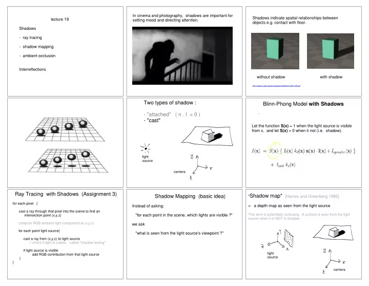
Interreflections In cinema and photography, shadows are important for setting mood and directing attention. Shadows indicate spatial relationships between
- bjects e.g. contact with floor.
http://www.cs.utah.edu/percept/papers/Madison:2001:UIS.pdf
without shadow with shadow
Two types of shadow :
- "attached" ( n . l < 0 )
- "cast"