
SLIDE 1
Testbench - Example: Register
Calcolatori Elettronici e Sistemi Operativi
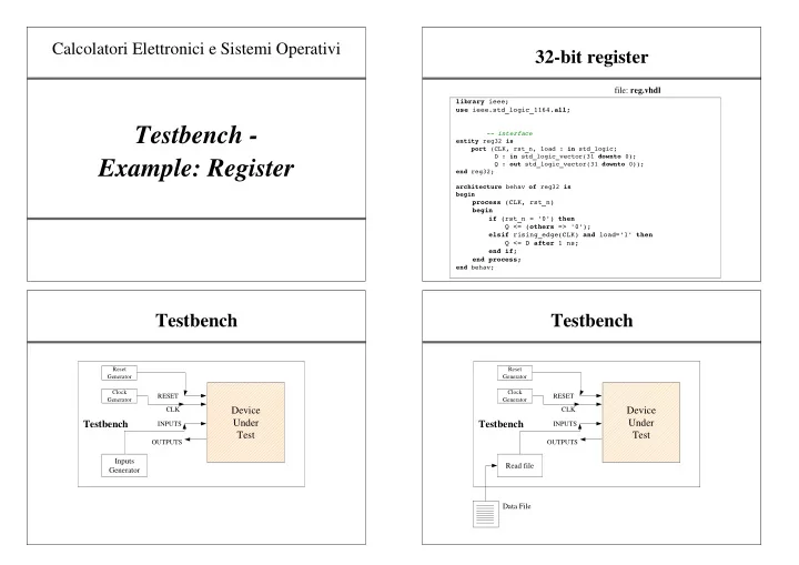
32-bit register
library ieee; use ieee.std_logic_1164.all;
- - interface
entity reg32 is port (CLK, rst_n, load : in std_logic; D : in std_logic_vector(31 downto 0); Q : out std_logic_vector(31 downto 0)); end reg32; architecture behav of reg32 is begin process (CLK, rst_n) begin if (rst_n = '0') then Q <= (others => '0'); elsif rising_edge(CLK) and load='1' then Q <= D after 1 ns; end if; end process; end behav;
file: reg.vhdl
Testbench
Testbench Device Under Test
RESET CLK INPUTS OUTPUTS
Inputs Generator
Reset Generator Clock Generator
Testbench
Testbench Device Under Test
RESET CLK INPUTS OUTPUTS
Read file Data File
Reset Generator Clock Generator