
SLIDE 1
lecture 6 Sequential circuits 2
- T flipflops, counters and timers (finishing last lecture)
- register array
- RAM
January 27, 2016
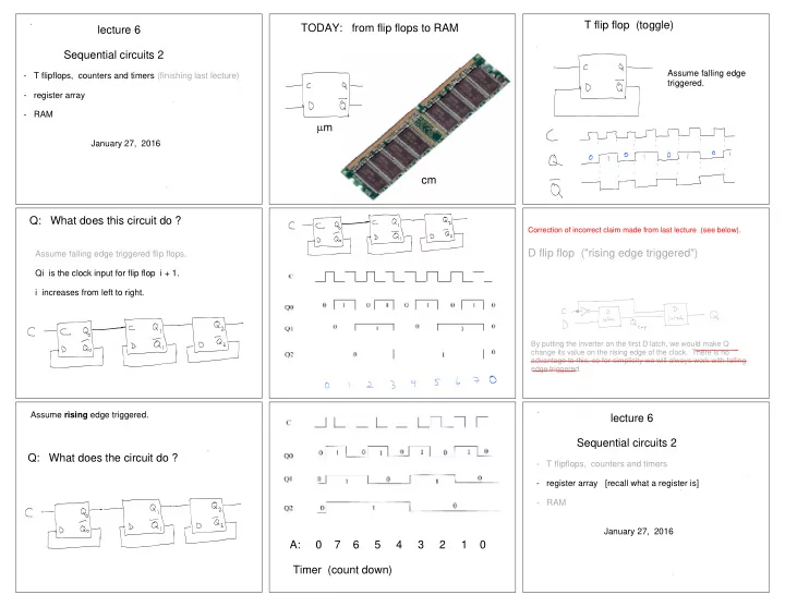
TODAY: from flip flops to RAM cm m T flip flop (toggle)
Assume falling edge triggered.
Q: What does this circuit do ?
Assume falling edge triggered flip flops. Qi is the clock input for flip flop i + 1. i increases from left to right.
Correction of incorrect claim made from last lecture (see below).
D flip flop ("rising edge triggered")
By putting the inverter on the first D latch, we would make Q change its value on the rising edge of the clock. There is no advantage to this, so for simplicity we will always work with falling edge triggered.
Assume rising edge triggered.
Q: What does the circuit do ? A: 0 7 6 5 4 3 2 1 0 Timer (count down) lecture 6 Sequential circuits 2
- T flipflops, counters and timers
- register array [recall what a register is]
- RAM