
SLIDE 1
Chapter 11: Flip-Flops
Computer Structure &
- Intro. to Digital Computers
c
- Dr. Guy Even
Tel-Aviv Univ.
– p.1
Goals
introduce clock signal. define edge-triggered flip-flops. discuss parameters of flip-flops: setup time, hold time, contamination delay, propagation delay. explain importance of critical segment. understand timing of a flip-flop.
- ther memory devices.
– p.2
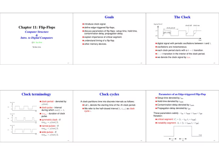
The Clock
logical level 1
pulse width
time clock fall clock rise clock period
digital signal with periodic oscillations between 0 and 1.
- scillations are instantaneous.
each clock period starts with a 0 → 1 transition. 1 → 0 transition in the interior of the clock period. we denote the clock signal by CLK.
– p.3
Clock terminology
logical level 1 time (A) (B) (C) logical level 1 time logical level 1 time
clock period - denoted by ϕ(CLK). clock pulse - interval during which CLK(t) = 1.
CLKpw - duration of clock
pulse. symmetric clock - if
CLKpw = ϕ(CLK)/2.
narrow pulses - if
CLKpw < ϕ(CLK)/2.
wide pulses - if
CLKpw > ϕ(CLK)/2.
– p.4
Clock cycles
A clock partitions time into discrete intervals as follows: Let ti denote the starting time of the ith clock period. We refer to the half-closed interval [ti, ti+1) as clock cycle i.
– p.5
Parameters of an Edge-triggered Flip-Flop
Setup-time denoted by tsu, Hold-time denoted by thold, Contamination-delay denoted by tcont, Propagation-delay denoted by tpd. These parameters satisfy −tsu < thold < tcont < tpd. Notation: critical segment: Ci = [ti − tsu, ti + thold]. instability segment: Ai = [ti + tcont, ti + tpd].
Ci clk Ai
– p.6