
SLIDE 1
EEE118: Electronic Devices and Circuits
Lecture X James E Green
Department of Electronic Engineering University of Sheffield j.e.green@sheffield.ac.uk
1/ 22 2/ 22 EEE118: Lecture 10
Review
Reviewed the principle of operation of Zener diodes (impact ionisation). Used the device (diode) characteristic to examine the
- perating point and linearity of a circuit.
Introduced the Zener diode shunt regulator circuit. Provided a method for designing the component values of the regulator. Introduced the idea of small signals and large signals. Considered the effects of distortion that large signals experience due to the non-linear nature of the diode characteristic with an audio example.
3/ 22 EEE118: Lecture 10
Outline
1 Linearising Circuits
Internal Resistance Improved Diode Model
2 Example Small Signal Diode Application 3 How does it look on the Characteristics? 4 The Transistor 5 Bipolar Junction Transistor 6 Numbering Systems
JEDEC Pro Electron
7 Review 8 Bear
4/ 22 EEE118: Lecture 10 Linearising Circuits
Circuit Linearisation
Diode Conducting:
10 V 1 kΩ
− +
0.7 V Vo
Diode Not Conducting:
10 V 1 kΩ Vo
In this model the diode is a perfect voltage source (0.7 V) with no internal resistance. The model can be improved by the addition of a resistance in series with the voltage source - remember Th´ evenin...
5/ 22 EEE118: Lecture 10 Linearising Circuits Internal Resistance
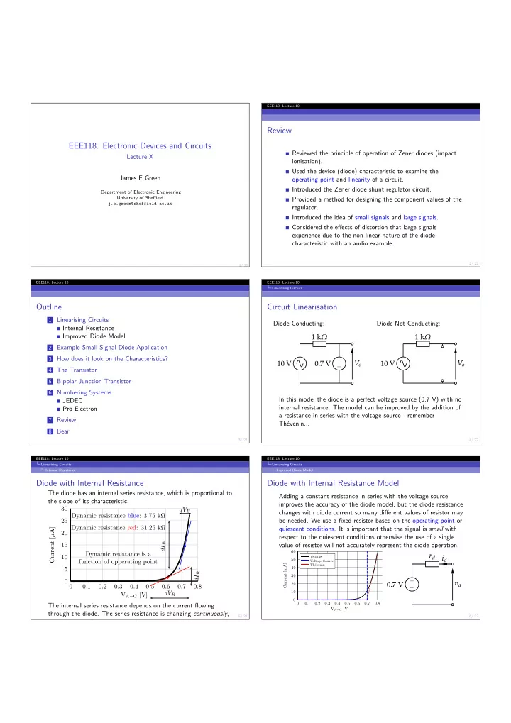
Diode with Internal Resistance
The diode has an internal series resistance, which is proportional to the slope of its characteristic. 5 10 15 20 25 30 0.1 0.2 0.3 0.4 0.5 0.6 0.7 0.8 VA−C [V] Current [µA]
b
dVR dIR
b
dIB dVB Dynamic resistance blue: 3.75 kΩ Dynamic resistance red: 31.25 kΩ Dynamic resistance is a function of opperating point The internal series resistance depends on the current flowing through the diode. The series resistance is changing continuously, but over a small region it is nearly constant.
6/ 22 EEE118: Lecture 10 Linearising Circuits Improved Diode Model
Diode with Internal Resistance Model
Adding a constant resistance in series with the voltage source improves the accuracy of the diode model, but the diode resistance changes with diode current so many different values of resistor may be needed. We use a fixed resistor based on the operating point or quiescent conditions. It is important that the signal is small with respect to the quiescent conditions otherwise the use of a single value of resistor will not accurately represent the diode operation.
10 20 30 40 50 60 0.1 0.2 0.3 0.4 0.5 0.6 0.7 0.8 VA−C [V] Current [mA]
1N4148 Voltage Source Th´ evenin