2 sin t
play

2 sin ( t ) v L inductors do not dissipate power because the - PDF document

EEE118: Lecture 2 Last Lecture: Review EEE118: Electronic Devices and Circuits Stated the Aims and Objectives of the course How electronic devices (diodes, transistors et al. work in Lecture II circuits Introduced some Circuit Terminology


  1. EEE118: Lecture 2 Last Lecture: Review EEE118: Electronic Devices and Circuits Stated the Aims and Objectives of the course How electronic devices (diodes, transistors et al. work in Lecture II circuits Introduced some Circuit Terminology (Voltage, Current, James Green Node, Branch) Introduced Engineering Units Department of Electronic Engineering University of Sheffield units use powers of three. 100 nA, 1 uA, 10 uA, 100 uA, j.e.green@sheffield.ac.uk 1 mA, 10 mA etc. Discussed two Passive Components, their physical construction (Resistors and Capacitors), relative price and performance. Considered the relationship between current and voltage in R & C in the time domain. 2/ 21 1/ 21 EEE118: Lecture 2 EEE118: Lecture 2 Passive Components Inductors
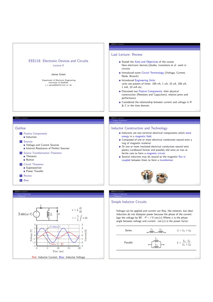
 Outline Inductor Construction and Technology Inductors are two terminal electrical components which store 1 Passive Components energy in a magnetic field. Inductors Composed of one or more electrical conductors wound onto a 2 Sources ring of magnetic material. Voltage and Current Sources Or one or more insulated electrical conductors wound onto Internal Resistance of Perfect Sources plastic/cardboard former and possibly slid onto an iron or 3 Source Transformation Theorems ferrite core to form a magnetic circuit. Th´ evenin Several inductors may be wound so the magnetic flux is Norton coupled between them to form a transformer. 4 Circuit Theorems Superposition Power Transfer 5 Review 6 Bear 3/ 21 4/ 21 EEE118: Lecture 2 EEE118: Lecture 2 Passive Components Passive Components Inductors Inductors Simple Inductor Circuits i v = L d i Voltage can be applied and current can flow, like resistors, but ideal d t + 2 sin ( ω t ) v L inductors do not dissipate power because the phase of the current i = 1 � − lags the voltage by 90 ◦ . P = I V cos ( φ ) Where φ is the phase v d t . L angle between voltage and current. cos ( φ ) is the power factor . 3 3 2 sin( ω t ) 2 2 L 1 L 2 Voltage [V] Current[A] Series L = L 1 + L 2 1 1 0 0 L 1 − 1 − 1 L = L 1 · L 2 − 2 − 2 Parallel sin( ω t − π 2 ) L 1 + L 2 L 2 − 3 − 3 0 5 10 15 20 Time [ms] Red: Inductor Current, Blue: Inductor Voltage 5/ 21 6/ 21

  2. EEE118: Lecture 2 EEE118: Lecture 2 Sources Sources Voltage and Current Sources Internal Resistance of Perfect Sources Voltage and Current Sources Voltage Source Internal Resistance What is the internal resistance of a perfect voltage source? Force a An ideal voltage source is a two terminal known current into a perfect voltage source and observe the R int circuit element supplying a fixed voltage and change in voltage, then use Ohm’s law to find the internal resistance. having zero internal resistance. A real voltage 6 source can only supply a finite current and + + V V d V = 1 d I R = 4 0 = ∞ behaves as an ideal source with a resistance in − − 5 series. It has non-zero internal resistance in d I = 5 − 1 = 4 4 Current [A] series with the ideal voltage source. 3 + An ideal current source is a two terminal 12 V 0 − 6 A d V = 12 − 12 = 0 − 2 circuit element supplying a fixed current and having infinite internal resistance. A real 1 current source can only supply the specified I I R int 0 current over a range of terminal voltages. It 0 2 4 6 8 10 12 14 16 18 20 22 24 Voltage [V] has a finite internal resistance in parallel with 1 ∞ = 0 Ω, so the internal resistance of a perfect voltage source is the ideal current source. zero. 7/ 21 8/ 21 EEE118: Lecture 2 EEE118: Lecture 2 Sources Source Transformation Theorems Internal Resistance of Perfect Sources Th´ evenin Current Source Internal Resistance Th´ evenin What is the internal resistance of a perfect current source? Force a Theorem known voltage across a perfect current source and observe the Any network of resistance elements and energy sources can be change in current, then use Ohm’s law to find the internal resistance. replace by a series combination of an ideal voltage source V T and 6 a resistance R T where V T is the open-circuit voltage of the circuit d V = 1 d I R = 0 10 = 0 and R T is the ratio of the open circuit voltage to the short circuit 5 current. d I = 3 − 3 = 0 4 Current [A] V 1 3 + − + 3 A 0 − 24 V − d V = 18 − 8 = 10 R 1 2 R T R 2 R 4 R 3 1 + V 2 R 5 − + V T − 0 V 5 0 2 4 6 8 10 12 14 16 18 20 22 24 + + V 3 V 4 + − − Voltage [V] − R 6 R 7 ? 0 = ∞ Ω, so the internal resistance of a perfect current source is R 8 + − infinite. V 6 9/ 21 10/ 21 EEE118: Lecture 2 EEE118: Lecture 2 Source Transformation Theorems Source Transformation Theorems Th´ evenin Norton Th´ evenin Method Norton Theorem Find V T by measurement or calculation of the voltage across Any network of resistance elements and energy sources can be the nodes of interest without anything connected (open-circuit) replace by a parallel combination of an ideal current source I T and a resistance R T where I T is the shot-circuit current of the circuit Find by measurement or calculation the current ( I sc ) that and R T is the ratio of the open circuit voltage to the short circuit flows when the nodes of interest are connected together current. (short-circuit). V 1 Divide V T by I sc to yield R T . − + For example, R 1 R 2 R 2 R 4 R 3 V T = V o = V i · I + R 1 + R 2 V 2 R 5 R 1 · R 2 − R 1 I T R T R 1 + R 2 I sc = V i + + V 5 + + V i V 3 V 4 R 1 − + − − − R 2 V i · − R 6 R 7 R 1 + R 2 R 2 V o R 1 R 2 R T = R 8 + R 1 + R 2 − V 6 11/ 21 12/ 21

  3. EEE118: Lecture 2 EEE118: Lecture 2 Source Transformation Theorems Source Transformation Theorems Norton Norton Norton Method Source Transformations Summary Find I N by measurement or calculation the current that flows Active and passive circuits can be treated as a “black box” and from one node to the other when they are short-circuit thought of in terms of their Th´ evenin equivalent voltage and series (connected together) resistance or Norton equivalent current and parallel resistance. Find by measurement or calculation the voltage ( V oc ) that appears across the nodes of interest when nothing is + E CC R 2 R 9 R 4 connected between them (open-circuit) 150 100 k 910 Q 13 2N4236 R T Q 2 Q 6 Q 9 Divide V oc by I N to yield R N . 2N4236 2N4236 2N4236 C 1 1 µ F R 5 C 3 100 k R 14 Q 1 Q 5 Q 12 i 1 D 1 i 2 R 11 0.68 µ F R 12 19 k 2N3819 2N3819 2N3819 + D 2 + For example, 20 20 OMC-V C 2 V 1 V 2 R 15 = R 6 0.1 µ F + − − − 200 − V T I N = V i 15 k A 1 A 2 D 4 + + D 5 OMC-V D 6 − Q 3 Q 7 Q 11 D 3 1N4729 1N4728 I Nexus Nexus C 4 2N5464 2N5464 2N5464 SQ-10A SQ-10A R 1 0.68 µ F R 1 R 13 R 1 20 k 91 k V i R 1 · R 2 Q 4 Q 8 Q 10 R 2 2N4239 2N4239 2N4239 Q 14 + R 1 R 1 + R 2 V oc = V i · V i 2N4239 R 10 R 1 + R 2 − R 3 910 150 R 2 V o R 1 R 2 − E CC R N = R 1 + R 2 13/ 21 14/ 21 EEE118: Lecture 2 EEE118: Lecture 2 Circuit Theorems Circuit Theorems Superposition Superposition Superposition Superposition Example Find the contribution of each source to the current flowing in R 2 . Theorem R 1 R 1 R 1 If a circuit consists of linear components (or components that can I R 2 I R 2 I R 2 be considered linear over a small range of voltage and current), the + + V 1 I 1 R 2 V 1 R 2 I 1 R 2 combined effect of several energy sources on the circuit is equal to − − the sum of the effects of each source acting alone. Both Sources Voltage Source Current Source The theorem implies that the sources should be considered 1 R 1 ?? I R 2 = V 1 · I R 2 = I 1 · R 1 + R 2 R 1 + R 2 independently, but does not say what to do with the ones we are not considering! Also by inspection the two expressions for I 2 have current flowing in the same direction so they are summed to yield, Consider the internal resistance of perfect voltage and current 1 R 1 sources (look back at the earlier slides). I R 2 = V 1 · + I 1 · R 1 + R 2 R 1 + R 2 Current sources are replaced by an infinite resistance open circuit. See Smith, R. J., and Dorf, R. C., Circuits Devices and Systems 5th ed., Wiley, 1992, pp. 56, dd. 621.3 Voltage sources are replaced by zero resistance short circuit. 15/ 21 16/ 21 EEE118: Lecture 2 EEE118: Lecture 2 Circuit Theorems Circuit Theorems Power Transfer Power Transfer Power Transfer Trial and Error 5 m Ω Let R L be, Consider an imperfect voltage source, where the internal resistance 1 2.5 mΩ is not zero. Is there an optimum resistance to transfer the + 2 . 5 V R L = 12 · 2 . 5+5 m Ω = 4 V . R L V R L maximum power from the source into the circuit? 12 V − P = V 2 4 2 R = 2 . 5 × 10 − 3 = 6 . 4 kW 2 5 mΩ 10 R T 9 5 V R L = 12 · 5+5 m Ω = 6 V . Two methods, 8 P = V 2 6 2 7 R = 5 × 10 − 3 = 7 . 2 kW Power [kW] 1 Trial and error with example 6 + 5 V R L numbers V T R L 3 7.5 mΩ 4 − 7 . 5 V R L = 12 · 7 . 5+5 m Ω = 7 . 2 V . 3 2 Mathematical derivation 2 P = V 2 7 . 2 2 R = 7 . 5 × 10 − 3 = 6 . 9 kW 1 P = I V and P = V 2 0 R and P = I 2 R 0 1 2 3 4 5 6 7 8 9 10 R L [mΩ] The maximum power transfer seems to occur when R L = R T . A more rigorous approach is desirable however. 17/ 21 18/ 21

Download Presentation
Download Policy: The content available on the website is offered to you 'AS IS' for your personal information and use only. It cannot be commercialized, licensed, or distributed on other websites without prior consent from the author. To download a presentation, simply click this link. If you encounter any difficulties during the download process, it's possible that the publisher has removed the file from their server.

Recommend


More recommend