
SLIDE 1
EEE118: Electronic Devices and Circuits
Lecture V James E. Green
Department of Electronic Engineering University of Sheffield j.e.green@sheffield.ac.uk
1/ 22 2/ 22 EEE118: Lecture 5
Last Lecture: Review
1 Finished the diode conduction state example question from
lecture four.
2 Introduced the Light Emitting Diode (LED) and direct vs.
indirect band-gap.
3 Performed a calculation to set the operating point of the LED. 4 Introduced the Zener Diode and considered the Zener effect
and Impact Ionisation.
5 Very briefly considered a voltage regulating circuit using a
Zener diode. (more later)
6 Introduced the Schottky Diode.
3/ 22 EEE118: Lecture 5
Outline
1 Pulse Circuits with Resistors & Capacitors
Pulse Circuit: “Low Pass” RC Example
2 Pulse Circuits with Diodes, Resistors & Capacitors
Pulse Circuits with Diodes Example Question Pulse Circuits with Diodes Example Solution
3 Five Diode Circuits
Peak Detector
4 Review 5 Bear
4/ 22 EEE118: Lecture 5 Pulse Circuits with Resistors & Capacitors
Pulse Circuits with Resistors & Capacitors
These sort of circuits are found in measurement systems for timing and can be used to help retrieve information from noisy systems (phase sensitive detection) and in digital systems (clock distribution etc.) and in high frequency applications such as radar systems. In this course we’re interested in understanding what goes on in the circuit and doing some calculations rather than
- derivations. Derivation is on the handout.
All first order RC circuits have a transient or time domain response that involves e( −t
τ ) where τ is dependent on the
circuit not on the properties of the pulse and t is time. τ (greek: tau) is the time constant which has units of seconds.
volts amps coluombs volts
= coulombs
coulombs seconds
= seconds
5/ 22 EEE118: Lecture 5 Pulse Circuits with Resistors & Capacitors Pulse Circuit: “Low Pass” RC Example
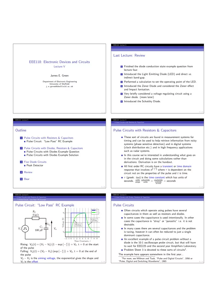
Pulse Circuit: “Low Pass” RC Example
Vi R2 5 kΩ C1 100 µF IC1 Vo
−2−1 0 1 2 3 4 5 6 7 8 9 Time Constants, τ Voltage [V] Rising Falling V2 V1
Vi Vo
Rising: Vo(t) = (V1 − V2)
- 1 − exp
- − t
τ
- + V2, t = 0 at the start
- f the pulse
Falling: Vo(t) = (V2 − V1)
- exp
- − t
τ
- + V2, t = 0 at the end of
the pulse V2 − V1 is the aiming voltage, the exponential gives the shape and V2 is the offset
6/ 22 EEE118: Lecture 5 Pulse Circuits with Diodes, Resistors & Capacitors
Pulse Circuits
Often circuits which operate using pulses have several capacitances in them as well as resistors and diodes. In some cases the capacitance is used intentionally. In other cases the capacitance is “stray” or “parasitic” i.e. it is not desirable. In many cases there are several capacitances and the problem is taxing, however it can often be reduced to just a single dominant capacitance. An excellent example of a pulse circuit problem without a diode is the 10:1 oscilloscope probe circuit, but that will have to wait for EEE225 and the second year Amplifiers Laboratory. Problem Sheet 3 is devoted to these sorts of circuits1. The example here appears somewhere in the first year...
1For more, see Millman and Taub, “Pulse and Digital Circuits”, 1956 or