
SLIDE 1
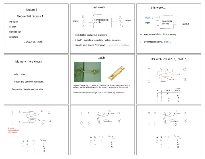
lecture 5 Sequential circuits 1
- RS latch
- D latch
- flipflops (D)
- registers
January 25, 2016
last week....
- truth tables and circuit diagrams
- 0 and 1 signals are (voltage) values on wires
- circuits take time to "compute" e.g. carries in addition
combinational circuits input
- utput
this week....
combinatorial circuits + memory synchronized by a clock C input
- utput
clock C sequential circuits
Memory (two kinds)
- write it down
- repeat it to yourself (feedback)