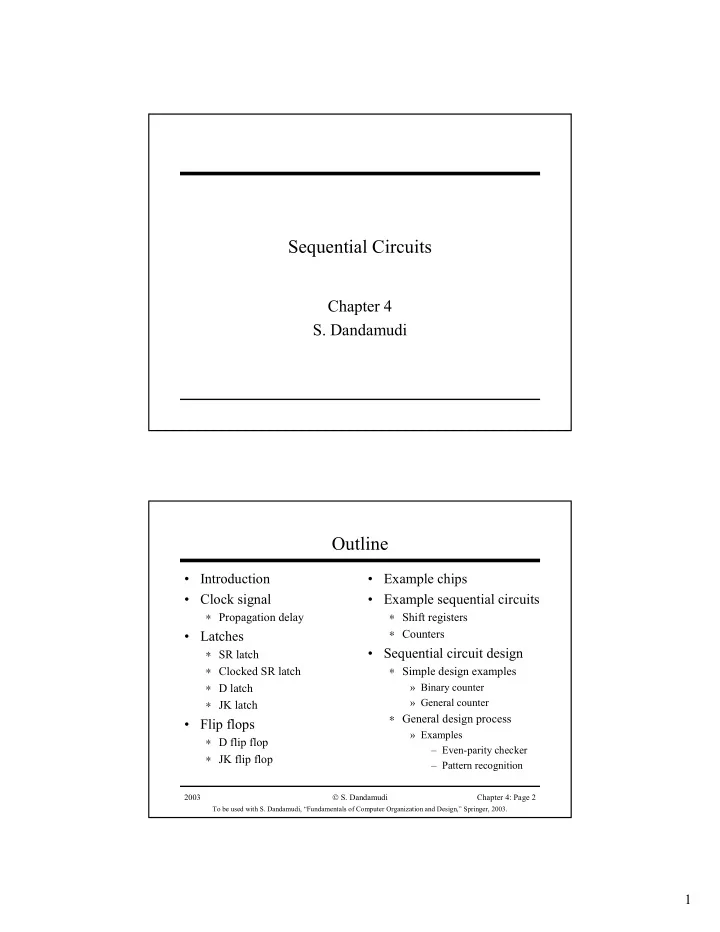

Sequential Circuits Chapter 4 S. Dandamudi Outline • Introduction • Example chips • Clock signal • Example sequential circuits ∗ Propagation delay ∗ Shift registers • Latches ∗ Counters • Sequential circuit design ∗ SR latch ∗ Clocked SR latch ∗ Simple design examples ∗ D latch » Binary counter » General counter ∗ JK latch ∗ General design process • Flip flops » Examples ∗ D flip flop – Even-parity checker ∗ JK flip flop – Pattern recognition 2003 S. Dandamudi Chapter 4: Page 2 To be used with S. Dandamudi, “Fundamentals of Computer Organization and Design,” Springer, 2003. 1
Introduction • Output depends on current as well as past inputs ∗ Depends on the history ∗ Have “memory” property • Sequential circuit consists of » Combinational circuit » Feedback circuit ∗ Past input is encoded into a set of state variables » Uses feedback (to feed the state variables) – Simple feedback – Uses flip flops 2003 S. Dandamudi Chapter 4: Page 3 To be used with S. Dandamudi, “Fundamentals of Computer Organization and Design,” Springer, 2003. Introduction (cont’d) Main components of a sequential circuit 2003 S. Dandamudi Chapter 4: Page 4 To be used with S. Dandamudi, “Fundamentals of Computer Organization and Design,” Springer, 2003. 2
Introduction (cont’d) • Feedback circuit can be ∗ A simple interconnection some outputs to input, or ∗ A combinational circuit with “memory” property » Uses flip-flops we discuss later • Feedback can potentially introduce instability 2003 S. Dandamudi Chapter 4: Page 5 To be used with S. Dandamudi, “Fundamentals of Computer Organization and Design,” Springer, 2003. Clock Signal • Digital circuits can be operated in ∗ Asynchronous mode » Circuits operate independently – Several disadvantages ∗ Synchronous mode » Circuits operate in lock-step » A common clock signal drives the circuits • Clock signal ∗ A sequence of 1s and 0s (ON and OFF periods) ∗ Need not be symmetric 2003 S. Dandamudi Chapter 4: Page 6 To be used with S. Dandamudi, “Fundamentals of Computer Organization and Design,” Springer, 2003. 3
Clock Signal (cont’d) 2003 S. Dandamudi Chapter 4: Page 7 To be used with S. Dandamudi, “Fundamentals of Computer Organization and Design,” Springer, 2003. Clock Signal (cont’d) • Clock serves two distinct purposes ∗ Synchronization point » Start of a cycle » End of a cycle » Intermediate point at which the clock signal changes levels ∗ Timing information » Clock period, ON, and OFF periods • Propagation delay ∗ Time required for the output to react to changes in the inputs 2003 S. Dandamudi Chapter 4: Page 8 To be used with S. Dandamudi, “Fundamentals of Computer Organization and Design,” Springer, 2003. 4
Clock Signal (cont’d) 2003 S. Dandamudi Chapter 4: Page 9 To be used with S. Dandamudi, “Fundamentals of Computer Organization and Design,” Springer, 2003. Latches • Can remember a bit • Level-sensitive (not edge-sensitive) A NOR gate implementation of SR latch 2003 S. Dandamudi Chapter 4: Page 10 To be used with S. Dandamudi, “Fundamentals of Computer Organization and Design,” Springer, 2003. 5
Latches (cont’d) • SR latch outputs follow inputs • In clocked SR latch, outputs respond at specific instances ∗ Uses a clock signal 2003 S. Dandamudi Chapter 4: Page 11 To be used with S. Dandamudi, “Fundamentals of Computer Organization and Design,” Springer, 2003. Latches (cont’d) • D Latch ∗ Avoids the SR = 11 state 2003 S. Dandamudi Chapter 4: Page 12 To be used with S. Dandamudi, “Fundamentals of Computer Organization and Design,” Springer, 2003. 6
Flip-Flops • Edge-sensitive devices ∗ Changes occur either at positive or negative edges Positive edge-triggered D flip-flop 2003 S. Dandamudi Chapter 4: Page 13 To be used with S. Dandamudi, “Fundamentals of Computer Organization and Design,” Springer, 2003. Flip-Flops (cont’d) • Notation ∗ Not strictly followed in the literature » We follow the following notation for latches and flip-flops Latches Flip-flops Low level High level Positive edge Negative edge 2003 S. Dandamudi Chapter 4: Page 14 To be used with S. Dandamudi, “Fundamentals of Computer Organization and Design,” Springer, 2003. 7
Flip-Flops (cont’d) JK flip-flop (master-slave) J K Q n+1 0 0 Q n 0 1 0 1 0 1 1 1 Q n 2003 S. Dandamudi Chapter 4: Page 15 To be used with S. Dandamudi, “Fundamentals of Computer Organization and Design,” Springer, 2003. 8
Recommend
More recommend