
1
Chapter 2
1
Instruction-Level Parallelism and Its Exploitation
Overview
- Instruction level parallelism
- Dynamic Scheduling Techniques
– Scoreboarding – Tomasulo’s Algorithm
- Reducing Branch Cost with Dynamic Hardware
2
- Reducing Branch Cost with Dynamic Hardware
Prediction
– Basic Branch Prediction and Branch-Prediction Buffers – Branch Target Buffers
- Overview of Superscalar and VLIW processors
CPI Equation
Pipeline CPI = Ideal pipeline CPI + Structural stalls + RAW stalls + WAR stalls + WAW stalls + Control stalls
Technique Reduces Loop unrolling Control stalls Basic pipeline scheduling RAW stalls
3
Dynamic scheduling with scoreboarding RAW stalls Dynamic scheduling with register renaming WAR and WAW stalls Dynamic branch prediction Control stalls Issuing multiple instructions per cycle Ideal CPI Compiler dependence analysis Ideal CPI and data stalls Software pipelining and trace scheduling Ideal CPI and data stalls Speculation All data and control stalls Dynamic memory disambiguation RAW stalls involving memory
Instruction Level Parallelism
- Potential overlap among instructions
- Few possibilities in a basic block
– Blocks are small (6-7 instructions) – Instructions are dependent
4
- Exploit ILP across multiple basic blocks
– Iterations of a loop
for (i = 1000; i > 0; i=i-1) x[i] = x[i] + s;
– Alternative to vector instructions
Basic Pipeline Scheduling
- Find sequences of unrelated instructions
- Compiler’s ability to schedule
– Amount of ILP available in the program – Latencies of the functional units
- Latency assumptions for the examples
– Standard MIPS integer pipeline
5
Standard MIPS integer pipeline – No structural hazards (fully pipelined or duplicated units – Latencies of FP operations:
Instruction producing result Instruction using result Latency FP ALU op FP ALU op 3 FP ALU op SD 2 LD FP ALU op 1 LD SD
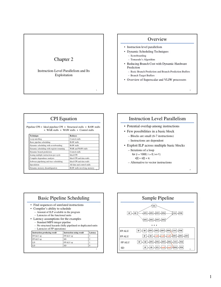
Sample Pipeline
IF ID FP1 FP2 FP3 FP4 EX
DM
WB FP1 FP2 FP3 FP4
6
. . .
IF ID FP1 FP2 FP3 FP4
DM
WB IF ID FP1 FP2 FP3 stall stall stall
FP ALU FP ALU
IF ID FP1 FP2 FP3 FP4
DM
WB IF ID DM WB EX stall stall