
SLIDE 1
MDTA’s I895 Bridge Project
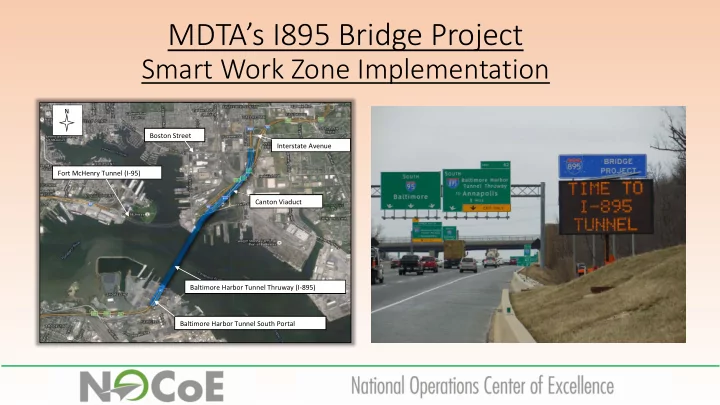
Smart Work Zone Implementation
Interstate Avenue Baltimore Harbor Tunnel South Portal
N
Baltimore Harbor Tunnel Thruway (I-895) Fort McHenry Tunnel (I-95) Boston Street Canton Viaduct
MDTAs I895 Bridge Project Smart Work Zone Implementation N Boston - - PowerPoint PPT Presentation
MDTAs I895 Bridge Project Smart Work Zone Implementation N Boston Street Interstate Avenue Fort McHenry Tunnel (I-95) Canton Viaduct Baltimore Harbor Tunnel Thruway (I-895) Baltimore Harbor Tunnel South Portal SWZ Smart Work Zone
Interstate Avenue Baltimore Harbor Tunnel South Portal
N
Baltimore Harbor Tunnel Thruway (I-895) Fort McHenry Tunnel (I-95) Boston Street Canton Viaduct
zone, and may also provide information on alternative routes in the corridor. The goal is to divert drivers away from the work zone when congestion exists.
motorists that traffic is slowed or stopped ahead.
depending on current operating conditions.
faster, allowing quicker response and clearance.
travel lane. It can also warn travelers that a work vehicle is exiting the travel lane and not to follow it into the work space.
information dissemination, modify operations, and facilitate evaluation.
Typical Equipment: 1 PCMS w/Doppler + 4 Sensors 1 Optional Added PCMS (1 mi before Taper)
Typical Benefits:
Reduce Chance of Rear End Crashes by 18-45%
Source: ARTBA Work Zone Safety Consortium (Sept 2015)
Project Limits:
Ave / Boston St (MM 11.65)
long)
Interstate Avenue Baltimore Harbor Tunnel South Portal
N
Baltimore Harbor Tunnel Thruway (I-895) Fort McHenry Tunnel (I-95) Boston Street Canton Viaduct
Scope of Work
Viaduct and Holabird Ave. Ramp Bridges
retaining walls
Advertisement: Summer 2017 NTP: April 2018 Main Bridge Construction: November 2018 Reduced Lanes only after I-95 Improvements complete After Thanksgiving Construction Complete: Summer 2021
MDTA
─ Capacity Improvements
─ Reduced capacity on I-695; Completed before Canton Viaduct Stage 2
─ Reduced capacity on I-895; Already Encourages diversion from I-895
GENERAL SYSTEM SPECIFICATION:
Sign(PVMS).
communications.
specifications.
4, including all associated sub-stages, OR as needed by engineer.
10 Portable Traffic Sensors I-895
Operational for Stages 2,3 and 4
13 Portable Variable Message Signs I-895 − I-95 I-695 − I-97 MD 295 − MD 2 US 40 − Moravia Road
13 Portable Variable Message Signs I-895 − I-95 I-695 − I-97 MD 295 − MD 2 US 40 − Moravia Road
Data Processing
Speed Thresholds Volumes Lane Occupancy
Email or Text
Avoid Conflicting Messages
$2,500 per day first 10 days $5,000 per day every day after 10
3rd Party TT Data
(From PCMS to Sensor)
Portable Sensors
(From Closest PCMS to Tunnel)
Combined 3rd Party & Portable Sensor Route Results in Cost-Effective Best Travel Time Data
Alt Rte Suggested TT > 3X Free Flow
Alt Rte Suggested TT > 3X Free Flow