SLIDE 1
1
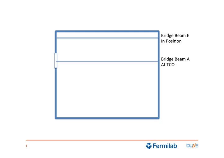
Bridge Beam A At TCO Bridge Beam E In Posi5on
SLIDE 2 2
APA#1 is loaded
At TCO
SLIDE 3
3
APA#1 is moved to its upstream loca5on
SLIDE 4 4
APA#2 is loaded
At TCO
SLIDE 5
5
APA#2 is moved to its midstream loca5on
SLIDE 6 6
APA#3 is loaded
At TCO
SLIDE 7
7
Bridge Beam A Is moved to Beam Right Posi5on
SLIDE 8
8
Bridge Beam B Is moved to TCO
SLIDE 9
9
Beam Right End Walls installed
SLIDE 10
10
Beam Right End Walls installed
SLIDE 11
11
Beam Right End Walls installed
SLIDE 12
12
Bridge Beam C posi5oned at TCO
SLIDE 13
13
Upstream CPA/FC unit posi5oned at TCO
SLIDE 14
14
Upstream CPA/FC unit posi5oned mid-point
SLIDE 15
15
US and Mid-stream CPA/FC units connected
SLIDE 16
16
US and Mid-stream CPA/FC units posi5oned
SLIDE 17
17
DS and Mid-stream CPA/FC units connected
SLIDE 18
18
Fully loaded Bridge Beam C moved to opera5ng posi5on
SLIDE 19
19
Posi5on Endwalls
SLIDE 20
20
Posi5on Endwalls
SLIDE 21
21
Deploy Top and BoKom Field Cage panels
SLIDE 22
22
Deploy Top and BoKom Field Cage panels
SLIDE 23
23
Deploy Top and BoKom Field Cage panels
SLIDE 24
24
Posi5on Endwall
SLIDE 25
25
Bridge Beam E Posi5oned at TCO
SLIDE 26
26
APA#4 installed at TCO
SLIDE 27
27
APA#6 frame moved to US posi5on
SLIDE 28
28
APA#5 frame moved into TCO
SLIDE 29
29
APA#5 frame moved to mid- stream
SLIDE 30
30
APA#4 moved into TCO
SLIDE 31
31
Fully loaded Bridge Beam E moved into posi5on
SLIDE 32
32
Bridge Beam D posi5oned at TCO
SLIDE 33
33
Beam leP End Walls move into posi5on
SLIDE 34
34
Beam leP End Walls move into posi5on
SLIDE 35
35
Beam leP End Walls move into posi5on
SLIDE 36
36
Beam leP End Walls move into posi5on
SLIDE 37
37
TCO is closed
SLIDE 38
38
Beam leP End Walls move into posi5on
SLIDE 39
39
Beam leP End Walls move into posi5on
SLIDE 40
40
Top and BoKom Field Cages deployed
SLIDE 41
41
Top and BoKom Field Cages deployed
SLIDE 42
42
Top and BoKom Field Cages deployed
SLIDE 43
43
Beam leP End Wall moved into posi5on