Overview Structural vs. functional test Definitions ECE 553: - - PDF document

overview
SMART_READER_LITE
LIVE PREVIEW

Overview Structural vs. functional test Definitions ECE 553: - - PDF document

9/25/2014 Overview Structural vs. functional test Definitions ECE 553: TESTING AND Completeness TESTABLE DESIGN OF Conditions for finding a test Algebras Algebras DIGITAL SYSTES DIGITAL SYSTES Types of Algorithms


slide-1
SLIDE 1

9/25/2014 1

ECE 553: TESTING AND TESTABLE DESIGN OF DIGITAL SYSTES DIGITAL SYSTES

Combinational ATPG Basics

Overview

  • Structural vs. functional test
  • Definitions
  • Completeness
  • Conditions for finding a test
  • Algebras

9/25/2014 2

  • Algebras
  • Types of Algorithms – classical
  • Complexity
  • Summary
  • Appendices

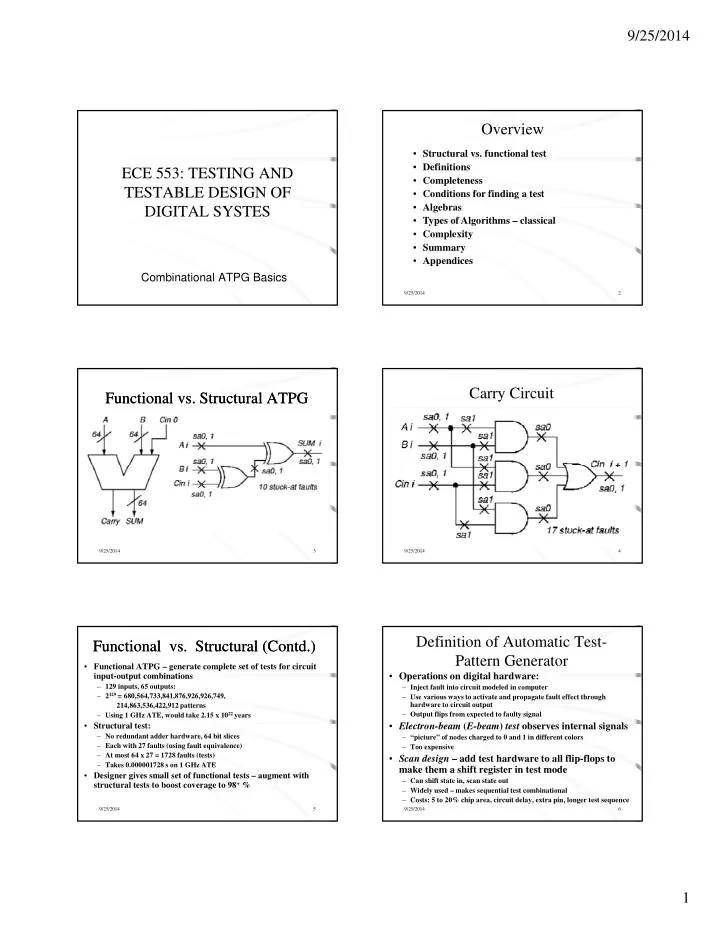
Functional vs. Structural ATPG Functional vs. Structural ATPG

9/25/2014 3

Carry Circuit

9/25/2014 4

Functional vs. Structural (Contd.) Functional vs. Structural (Contd.)

  • Functional ATPG – generate complete set of tests for circuit

input-output combinations

– 129 inputs, 65 outputs: – 2129 = 680,564,733,841,876,926,926,749, 214,863,536,422,912 patterns – Using 1 GHz ATE, would take 2.15 x 10²² years

St t l t t

9/25/2014 5

  • Structural test:

– No redundant adder hardware, 64 bit slices – Each with 27 faults (using fault equivalence) – At most 64 x 27 = 1728 faults (tests) – Takes 0.000001728 s on 1 GHz ATE

  • Designer gives small set of functional tests – augment with

structural tests to boost coverage to 98+ %

Definition of Automatic Test- Pattern Generator

  • Operations on digital hardware:

– Inject fault into circuit modeled in computer – Use various ways to activate and propagate fault effect through hardware to circuit output – Output flips from expected to faulty signal

El t b (E b ) t t b i t l i l

9/25/2014 6

  • Electron-beam (E-beam) test observes internal signals

– “picture” of nodes charged to 0 and 1 in different colors – Too expensive

  • Scan design – add test hardware to all flip-flops to

make them a shift register in test mode

– Can shift state in, scan state out – Widely used – makes sequential test combinational – Costs: 5 to 20% chip area, circuit delay, extra pin, longer test sequence

slide-2
SLIDE 2

9/25/2014 2

Algorithm Completeness

  • Definition: Algorithm is complete if it

ultimately can search entire binary (decision) space, as needed, to generate a test

  • Untestable fault or Undetectable fault

no test

9/25/2014 7

  • Untestable fault or Undetectable fault – no test

for it even after entire space is searched

  • Combinational circuits only – untestable

faults are redundant, showing the presence of unnecessary hardware

Notation Notation

Symbol D D

Meaning 1/0 0/1 0/0 Failing Circuit 1 Good Circuit 1 Roth’s

9/25/2014 8

1 X G0 G1 F0 F1

0/0 1/1 X/X 0/X 1/X X/0 X/1 1 X X X 1 1 X 1 X X Algebra Muth’s Additions

Roth’s and Muth’s Higher-Order Algebras Roth’s and Muth’s Higher-Order Algebras

  • Represent two machines, which are simulated

simultaneously by a computer program:

– Good circuit machine (1st value) – Bad circuit machine (2nd value)

9/25/2014 9

  • Better to represent both in the algebra:

– Need only 1 pass of ATPG to solve both – Good machine values that preclude bad machine values become obvious sooner & vice versa

  • Needed for complete ATPG:

– Combinational: Multi-path sensitization, Roth Algebra – Sequential: Muth Algebra -- good and bad machines may have different initial values due to fault

Conditions for Finding a Test

  • Fault excitation – the signal value at the fault

site must be different from the value of the stuck-at fault (thus fault site must contain a D or a D)

  • The fault effect must be propagated to a

9/25/2014 10

The fault effect must be propagated to a primary output (A D or a D must appear at the

  • utput)
  • Some simple observations

– There must be at least a D or a D on some circuit nets) – D’s must form a chain to some output

Exhaustive Algorithm

  • For n-input circuit, generate all 2n input

patterns

  • Infeasible, unless circuit is partitioned into

f l i ith 15 i t

9/25/2014 11

cones of logic, with 15 inputs

– Perform exhaustive ATPG for each cone – Misses faults that require specific activation patterns for multiple cones to be tested

Random-Pattern Generation Random-Pattern Generation

  • Flow chart for

method

  • Use to get tests

for 60-80% of

9/25/2014 12

faults, then switch to D- algorithm or

  • ther ATPG

for rest

slide-3
SLIDE 3

9/25/2014 3

Boolean Difference Symbolic Method (Sellers et al.) Boolean Difference Symbolic Method (Sellers et al.)

9/25/2014 13

g = G (X1, X2, …, Xn) for the fault site fj = Fj (g, X1, X2, …, Xn) 1 j m Xi = 0 or 1 for 1 i n

≤ ≤ ≤ ≤

  • Shannon’s Expansion Theorem:

F (X1, X2, …, Xn) = X2 F (X1, 1, …, Xn) + X2 F (X1, 0, …, Xn)

  • Boolean Difference (partial derivative):

Boolean Difference (Sellers, Hsiao, Bearnson) Boolean Difference (Sellers, Hsiao, Bearnson)

9/25/2014 14

Fj g

  • Fault Detection Requirements for g stuck-at 0:

G (X1, X2, …, Xn) = 1 Fj g

= Fj (1, X1, X2, …, Xn) Fj (0, X1, …, Xn) = Fj (1, X1, X2, …, Xn) Fj (0, X1, …, Xn) = 1

∂ ∂ ⊕ ∂ ∂ ⊕

Path Sensitization Method - Example Path Sensitization Method - Example

1 Fault Sensitization 2 Fault Propagation 3 Line Justification

9/25/2014 15

Path Sensitization Method -Example Path Sensitization Method -Example

  • Try path f – h – k – L. This path is blocked at j,

since there is no way to justify the 1 on i

D 1

9/25/2014 16

1 D 1 1 D D D

Path Sensitization Method Path Sensitization Method

  • Try simultaneous paths f – h – k – L and

g – i – j – k – L. These paths blocked at k because D-frontier (chain of D or D) disappears

D 1

9/25/2014 17

1 D D D D 1 1

Path Sensitization Method Circuit Example Path Sensitization Method Circuit Example

  • Final try: path g – i – j – k – L – test found!

9/25/2014 18

D D D 1 D D 1 1

slide-4
SLIDE 4

9/25/2014 4

Computational Complexity

  • Ibarra and Sahni analysis – NP-Complete

(no polynomial expression found for compute time, presumed to be exponential)

  • Worst case:

9/25/2014 19

W no_pi inputs, 2no_pi input combinations no_ff flip-flops, 4no_ff initial flip-flop states (good machine 0 or 1 bad machine 0 or 1) work to forward or reverse simulate n logic gates α n

  • Complexity: O (n x 2 no_pi x 4 no_ff)

×

Summary

  • Basic definitions explained
  • Developed notation and required algebra that

will be used for test generation and fault simulation

9/25/2014 20

  • Basics of test generation developed
  • Complexity of test generation addressed
  • Appendix contains historical reference to the

stuck-at fault model, an example of BDD, an instantiation of SAT problem.

Appendices

9/25/2014 21

Origins of Stuck-Faults

  • Eldred (1959) – First use of structural testing

for the Honeywell Datamatic 1000 computer

  • Galey, Norby, Roth (1961) – First publication
  • f stuck at 0 and stuck at 1 faults

9/25/2014 22

  • f stuck-at-0 and stuck-at-1 faults
  • Seshu & Freeman (1962) – Use of stuck-faults

for parallel fault simulation

  • Poage (1963) – Theoretical analysis of stuck-at

faults

Circuit and Binary Decision Tree Circuit and Binary Decision Tree

9/25/2014 23

Binary Decision Diagram Binary Decision Diagram

  • BDD – Follow path from source to sink node –

product of literals along path gives Boolean value at sink

  • Rightmost path: A B C = 1

P bl Si i l

9/25/2014 24

  • Problem: Size varies greatly

with variable order

slide-5
SLIDE 5

9/25/2014 5

History of Algorithm Speedups History of Algorithm Speedups

Algorithm D-ALG PODEM FAN TOPS

  • Est. speedup over D-ALG

(normalized to D-ALG time) 1 7 23 292 Year 1966 1981 1983 1987

9/25/2014 25

TOPS SOCRATES Waicukauski et al. EST TRAN Recursive learning Tafertshofer et al. 292 1574 ATPG System 2189 ATPG System 8765 ATPG System 3005 ATPG System 485 25057 1987 1988 1990 1991 1993 1995 1997 † † † †

Analog Fault Modeling Impractical for Logic ATPG

  • Huge # of different possible analog faults in

digital circuit

  • Exponential complexity of ATPG algorithm – a

20 flip-flop circuit can take days of computing

9/25/2014 26

20 flip flop circuit can take days of computing

– Cannot afford to go to a lower-level model

  • Most test-pattern generators for digital circuits

cannot even model at the transistor switch level (see textbook for 5 examples of switch-level ATPG)

Boolean Satisfiability Boolean Satisfiability

  • 2SAT: xi xj + xj xk + xl xm … = 0

x x + x x + x x = 0

. . .

9/25/2014 27

xp xy + xr xs + xt xu … = 0

  • 3SAT: xi xj xk + xj xk xl + xl xm xn … = 0

xp xy + xr xs xt + xt xu xv … = 0

. . .

Satisfiability Example for AND Gate Satisfiability Example for AND Gate

Σ ak bk ck = 0

(non-tautology) or

Π (ak + bk + ck) = 1 (satisfiability)

9/25/2014 28

  • AND gate signal relationships: Cube:

– If a = 0, then z = 0 a z – If b = 0, then z = 0 b z – If z = 1, then a = 1 AND b = 1 z a b – If a = 1 AND b = 1, then z = 1 a b z

  • Sum to get: a z + b z + a b z = 0

(third relationship is redundant with 1st two)

Pseudo-Boolean and Boolean False Functions

  • Pseudo-Boolean function: use ordinary + -- integer

arithmetic operators

– Complementation of x represented by 1 – x F 2 b b b

9/25/2014 29

– Fpseudo—Bool = 2 z + a b – a z – b z – a b z = 0

  • Energy function representation: let any variable be in

the range (0, 1) in pseudo-Boolean function

  • Boolean false expression:

fAND (a, b, z) = z (ab) = a z + b z + a b z

AND Gate Implication Graph AND Gate Implication Graph

  • Really efficient
  • Each variable has 2 nodes, one for each literal
  • If … then clause represented by edge from if literal

to then literal

  • Transform into transitive closure graph

Wh d ll h bl

9/25/2014 30

– When node true, all reachable states are true

  • ANDing operator used for 3SAT relations

∧ ∧