Lecture 12 Logistics HW4 was due yesterday HW5 was out yesterday - - PDF document

lecture 12
SMART_READER_LITE
LIVE PREVIEW

Lecture 12 Logistics HW4 was due yesterday HW5 was out yesterday - - PDF document

Lecture 12 Logistics HW4 was due yesterday HW5 was out yesterday (due next Wednesday) HW5 was out yesterday (due next Wednesday) Feedback: thank you! Things to work on: Big picture, Book chapters, Exam comments Last


slide-1
SLIDE 1

Lecture 12

Logistics

HW4 was due yesterday HW5 was out yesterday (due next Wednesday) HW5 was out yesterday (due next Wednesday) Feedback: thank you! Things to work on: Big picture, Book chapters, Exam comments

Last lecture

Adders

Today

Cl ifi ti f Add

1

CSE370, Lecture 13 Clarification of Adders Summary of Combinational Logic Introduction to Sequential Logic

The basic concepts A simple example

12

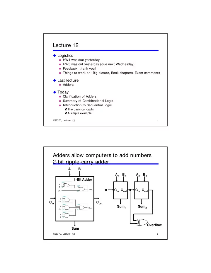
Adders allow computers to add numbers 2-bit ripple-carry adder

A1 B1 A B A2 B2 Cout Cin Sum1

Ci A Cout Cin B

AND2 OR3 11 AND2

Cin Sum B A

33 XOR 32 XOR

Cout Cin 1-Bit Adder Sum2 Cout Cin

2

CSE370, Lecture 13

A B Cin

13 AND2 12 14

Sum Overflow

11 12

slide-2
SLIDE 2

XOR

Problem: Ripple-carry delay

Carry propagation limits adder speed (we want to add fast)

Cin Cin Sum B A

33 XOR 32 XOR

A Cin B

AND2 OR3 11 AND2

@0 @0 A0 B0 S0 @2 A1 B1 C1 @2 S1 @3 A2 C2 @4 S2 @5 @0 @2N @0 @2N @2N+1 @2N+2

3

CSE370, Lecture 13 A B Cin A Cout

13 AND2 12 14

Cout takes two gate delays Cin arrives late

A2 B2 S2 @5 A3 B3 C3 @6 S3 @7 Cout @8 @0 @2N @0 @0 @2N 2 11 12 A

XOR

One Solution: Carry lookahead logic

Get Pi (propagate) and Gi (generate)

@0 Cin

Pi

@1

Cin Sum B A

33 XOR 32

A Cout Cin B

AND2 OR3 11 AND2

@0 @0 A0 B0 S0 @2 A1 B1 C1 @2 S1 @3 A2 C2 @4 S2 @5 @0 @2N @0 @2N @2N+1 @2N+2

P0 G0 P1 G1 P2 @2 @3 @3 @4 @4 4

CSE370, Lecture 13 A B Cin Cout

13 AND2 12 14

A2 B2 S2 @5 A3 B3 C3 @6 S3 @7 C4@8 @2N @0 @0 12

Gi C2 = G1 + P1C1 C3 = G2 + P2C2

P2 G2 P3 G3

C4 = G3 + P3C3 = G1 + P1G0 + P1P0C0 = G2 + P2G1 + P2P1G0 + P2P1P0C0 = G3 + P3G2 + P3P2G1 + P3P2P1G0 + P3P2P1P0C0 C1 = G0 + P0C0

@3 @3 @4 @

slide-3
SLIDE 3

Cascaded carry-lookahead adder (in your HW5)

4 four-bit adders with internal carry lookahead

Second level lookahead extends adder to 16 bits

@3 @2 @3 @2 @3 @2 @3 @2 A[15-12] B[15-12] C12 S[15-12] A[11-8] B[11-8] C8 S[11-8] A[7-4] B[7-4] C4 S[7-4] @7 @8 @8 A[3-0] B[3-0] C0 S[3-0] @0 @4 4 4 4 P G 4-bit Adder 4 4 4 P G 4-bit Adder 4 4 4 P G 4-bit Adder 4 4 4 P G 4-bit Adder

5

CSE370, Lecture 13

Lookahead Carry Unit C0 P0 G0 P1 G1 P2 G2 P3 G3 C3 C2 C1 C0 P3-0 G3-0 C4 @4 @5 @5 @5 @5 @3 @0 C16

11 12

Another solution: Carry-select adder

Redundant hardware speeds carry calculation

Compute two high-order sums while waiting for carry-in (C4) Select correct high-order sum after receiving C4 4-bit adder [7:4] C8 1 C8 adder high adder low 4-bit adder [7:4] Select correct high-order sum after receiving C4

@3 @3

I0 S I1 Z

@4 @3 @4 @4 @6 6

CSE370, Lecture 13 4-Bit Adder [3:0] C0 C4 five 2:1 muxes 1 1 1 1 1 C8 S7 S6 S5 S4 S3 S2 S1 S0 11

@3 @4 @4 @6 @5

12

slide-4
SLIDE 4

We've finished combinational logic...

What you should know

Twos complement arithmetic Truth tables Truth tables Basic logic gates Schematic diagrams Timing diagrams Minterm and maxterm expansions (canonical, minimized) de Morgan's theorem AND/OR to NAND/NOR logic conversion K-maps, logic minimization, don't cares

7

CSE370, Lecture 13 K maps, logic minimization, don t cares Multiplexers/demultiplexers PLAs/PALs ROMs Adders 11

We had no way to store memory: When the input changed, the output changed Next: Sequential logic can store memory…

12

Sequential Logic (next 5 weeks!)

We learn the details

Latches, flip-flops, registers (storage) Shift registers counters (we can count now!) Shift registers, counters (we can count now!) State machines Timing and timing diagrams

timing more important than combinational logic

Synchronous and asynchronous inputs

Metastability (problem!)

Moore and Mealy machines (types of state machines)

8

CSE370, Lecture 13 More... 12

slide-5
SLIDE 5

Sequential versus combinational

B A C B clock

Apply fixed inputs A, B Wait for clock edge Observe C Wait for another clock edge Ob C i

9

CSE370, Lecture 13

Observe C again Combinational: C will stay the same Sequential: C may be different

12

Sequential versus combinational (again)

Combinational systems are memoryless

Outputs depend only on the present inputs

Sequential systems have memory

Outputs depend on the present and the previous inputs

Inputs Outputs System

10

CSE370, Lecture 13

Inputs Outputs System Feedback

12

slide-6
SLIDE 6

Synchronous sequential systems

Memory holds a system’s state

Changes in state occur at specific times A periodic signal times or clocks the state changes A periodic signal times or clocks the state changes The clock period is the time between state changes

B A C clock

State changes occur at rising edge of clock

11

CSE370, Lecture 13

period duty cycle = pulsewidth/ period (here it is 50% ) pulsewidth

clock

12

Steady-state abstraction

Outputs retain their settled values

The clock period must be long enough for all voltages to

settle to a steady state before the next state change settle to a steady state before the next state change

B A C clock

Clock hides transient behavior

12

CSE370, Lecture 13

clock C

Settled value

12

slide-7
SLIDE 7

What did I just say about sequential logic?

Has clock

Synchronous = clocked Exception: Asynchronous Exception: Asynchronous

Has state

State = memory

Employs feedback Assumes steady-state signals

Signals are valid after they have settled

13

CSE370, Lecture 13 Signals are valid after they have settled State elements hold their settled output values 12

Example: A sequential system

Door combination lock

Enter 3 numbers in sequence and the door opens If there is an error the lock must be reset If there is an error the lock must be reset After the door opens the lock must be reset Inputs: Sequence of numbers, reset Outputs: Door open/close Memory: Must remember the combination

14

CSE370, Lecture 13 12

slide-8
SLIDE 8

Understand the problem

Consider I/O and unknowns

How many bits per input? How many inputs in sequence? How many inputs in sequence? How do we know a new input is entered? How do we represent the system states?

reset value new

15

CSE370, Lecture 13

  • pen/closed

clock

12

Implement using sequential logic

Behavior

Clock tells us when to look at inputs

After inputs have settled After inputs have settled

Sequential: Enter sequence of numbers Sequential: Remember if error occurred

Need a finite-state diagram

Assume synchronous inputs State sequence

Enter 3 numbers serially b f d reset value new

16

CSE370, Lecture 13

Remember if error occurred

All states have outputs

Lock open or closed

  • pen/closed

clock

12

slide-9
SLIDE 9

Finite-state diagram

States: 5

Each state has outputs

O t

t / l d

Inputs: reset, new, results of

comparisons

Assume synchronous inputs

Outputs: open/closed y p

C1!= value & new C2!= value C3!= value closed ERR

We use state diagrams to represent sequential logic System transitions between finite numbers of states

17

CSE370, Lecture 13 closed closed closed C1= = value & new C2= = value & new C3= = value & new & new & new & new reset not new not new not new S1 S2 S3 OPEN

  • pen

12

Separate data path and control

Data path

Stores combination Compares inputs with

Control

Finite state-machine controller Control for data path Compares inputs with

combination

Control for data path State changes clocked

reset new C1 C2 C3

multiplexer

mux control 4 4 4

18

CSE370, Lecture 13

  • pen/closed

comparator

value equal

multiplexer controller

clock 4 4

12

slide-10
SLIDE 10

Refine diagram; generate state table

Refine state diagram to

include internal structure

closed not equal not equal ERR closed mux= C1 reset equal & new & new not equal & new not equal & new not new not new not new S1 S2 S3 OPEN closed mux= C2 equal & new closed mux= C3 equal & new

  • pen

reset new equal state state mux

  • pen/closed

next

19

CSE370, Lecture 13

Generate

state table

reset new equal state state mux

  • pen/closed

1 – – – S1 C1 closed – S1 S1 C1 closed 1 S1 ERR – closed 1 1 S1 S2 C2 closed ... 1 1 S3 OPEN –

  • pen

...

12