
SLIDE 1
12.1
Unit 12
Adders & Arithmetic Circuits
12.2
Learning Outcomes
- I understand what gates are used to design half and
full adders
- I can build larger arithmetic circuits from smaller
building blocks
12.3
ADDERS
12.4
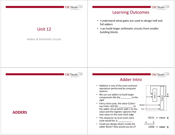
Adder Intro
- Addition is one of the most common
- perations performed by computer
systems
- We can use adders to build larger
components like the ________ to the right
- Every clock cycle, the value Q (let's
say 4-bits: Q[3:0]), ___________ to the adder circuit which adds 1 to the value and the register captures that new value on the next clock edge
- The sequence on Q on each clock
cycle would be: 0, __________…
- Could you design what's inside the
adder block? How would you do it? 0111 + 1 1000 = curr Q = next Q
Register 1 Adder (+) Q RESET CLK