
SLIDE 1
IE1206 Embedded Electronics
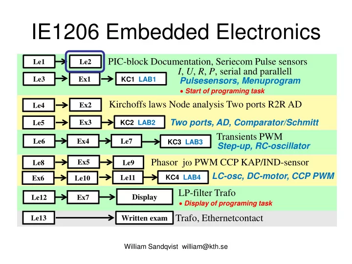
Transients PWM Phasor jω PWM CCP KAP/IND-sensor
Le1 Le3 Le6 Le8 Le2 Ex1 Le9 Ex4 Le7
Written exam
William Sandqvist william@kth.se
PIC-block Documentation, Seriecom Pulse sensors I, U, R, P, serial and parallell
Ex2 Ex5
Kirchoffs laws Node analysis Two ports R2R AD Trafo, Ethernetcontact
Le13
Pulsesensors, Menuprogram
Le4
KC1 LAB1 KC3 LAB3 KC4 LAB4
Ex3 Le5
KC2 LAB2
Two ports, AD, Comparator/Schmitt Step-up, RC-oscillator
Le10 Ex6
LC-osc, DC-motor, CCP PWM
LP-filter Trafo
Le12 Ex7
Display
Le11
- Start of programing task
- Display of programing task