IE1206 Embedded Electronics PIC-block Documentation, Seriecom Pulse - - PowerPoint PPT Presentation

ie1206 embedded electronics
SMART_READER_LITE
LIVE PREVIEW

IE1206 Embedded Electronics PIC-block Documentation, Seriecom Pulse - - PowerPoint PPT Presentation

IE1206 Embedded Electronics PIC-block Documentation, Seriecom Pulse sensors Le1 Le2 I , U , R , P , serial and parallel KC1 LAB1 Pulse sensors, Menu program Le3 Ex1 Start of programing task Ex2 Le4 Kirchhoffs laws Node


slide-1
SLIDE 1

IE1206 Embedded Electronics

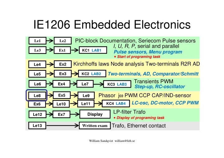
Transients PWM Phasor jω PWM CCP CAP/IND-sensor

Le1 Le3 Le6 Le8 Le2 Ex1 Le9 Ex4 Le7

Written exam

William Sandqvist william@kth.se

PIC-block Documentation, Seriecom Pulse sensors I, U, R, P, serial and parallel

Ex2 Ex5

Kirchhoffs laws Node analysis Two-terminals R2R AD Trafo, Ethernet contact

Le13

Pulse sensors, Menu program

Le4

KC1 LAB1 KC3 LAB3 KC4 LAB4

Ex3 Le5

KC2 LAB2

Two-terminals, AD, Comparator/Schmitt Step-up, RC-oscillator

Le10 Ex6

LC-osc, DC-motor, CCP PWM

LP-filter Trafo

Le12 Ex7

Display

Le11

  • Start of programing task
  • Display of programing task
slide-2
SLIDE 2

William Sandqvist william@kth.se

Easy to generate a sinusoidal voltage

Our entire power grid works with sinusoidal voltage. When the loop rotates with constant speed in a magnetic field a sine wave is generated. So much easier, it can not be …

slide-3
SLIDE 3

William Sandqvist william@kth.se

The sine wave – what do you remember?

period T time t y amplitude top Y , ˆ RMS Y 2 ˆ 1 2 ) sin( ˆ ) ( Y Y T f f t Y t y = = = = π ω ω

slide-4
SLIDE 4

William Sandqvist william@kth.se

(11.1) Phase ϕ

) sin( ˆ ) ( ϕ ω + = t Y t y

If a sine curve does not begin with 0 the function expression has a phase angle ϕ. Specify this function mathematically:

) 1000 2 sin( 6 ) ( ϕ π + ⋅ ⋅ ⋅ = t t u

y

) 30 ( rad 52 , 6 3 arcsin ) sin( 6 3 ) ( ° = =

  • =

= = ϕ ϕ u ) 52 , 6283 sin( 6 ) ( + ⋅ ⋅ = t t u

slide-5
SLIDE 5

William Sandqvist william@kth.se

Apples and pears?

In circuit analyses it is common (eg. in textbooks) to expresses the angle of the sine function mixed in radians ω·t [rad] and in degrees ϕ [°]. This is obviously improper, but practical (!). The user must "convert" phase angle to radians to calculate the sine function value for any given time t. (You have now been warned …)

) 30 6283 sin( 6 ) ( ° + ⋅ ⋅ = t t u

Conversion: x[°]= x[rad] ⋅57,3 x[rad]= x[°]⋅0,017 ? ?

slide-6
SLIDE 6

William Sandqvist william@kth.se

slide-7
SLIDE 7

William Sandqvist william@kth.se

Mean and effective value

T t t u U t t u U

T T T

  • =

= =

2 1 med

d ) ( d ) (

All pure AC voltages, has the mean value 0.

  • More interesting is the effective value – root

mean square, rms.

slide-8
SLIDE 8

William Sandqvist william@kth.se

(11.2) Example. RMS.

V 63 , 1 10 15 10 5 8 10 15 10 5 ) ) 2 ( 2 ( d ) (

3 3 3 3 2 2 2

= ⋅ ⋅ ⋅ = ⋅ ⋅ ⋅ + − + = =

− − − −

  • T

t t u U

T

The rms value is what is normally used for an alternating voltage U. 1,63 V effective value gives the same power in a resistor as a 1,63 V pure DC voltage would do.

RMS, effective value

slide-9
SLIDE 9

William Sandqvist william@kth.se

Sine wave effective value

2 1 2 1 d ) ( sin2 = =

  • x

x ) ( sin 2 x

2 1

  • Effective value is often called RMS ( Root Mean Square ).

sin2 has the mean value ½ Therefore:

2 ˆ U U =

RMS, effective value

  • Ex. 11.3
slide-10
SLIDE 10

William Sandqvist william@kth.se

slide-11
SLIDE 11

William Sandqvist william@kth.se

Addition of sinusoidal quantities

) sin( ˆ

1 1 1

ϕ ω + = t A y ) sin( ˆ

2 2 2

ϕ ω + = t A y ?

2 1

= + y y

slide-12
SLIDE 12

William Sandqvist william@kth.se

Addition of sinusoidal quantities

When we shall apply the circuit laws on AC circuits, we must add the sines. The sum of two sinusoidal quantities of the same frequency is always a new sine of this frequency, but with a new amplitude and a new phase angle. ( Ooops! The result of the rather laborious calculations are shown below).

  • +

+ + ⋅ − + + = = + = + ⋅ = + ⋅ = ) cos( A ˆ ) cos( A ˆ ) sin( A ˆ ) sin( A ˆ arctan sin ) cos( A ˆ A ˆ 2 A ˆ A ˆ ) ( ) ( ) ( ) sin( A ˆ ) ( ) sin( A ˆ ) (

2 2 1 1 2 2 1 1 2 1 2 1 2 2 2 1 2 1 2 2 2 1 1 1

ϕ ϕ ϕ ϕ ω ϕ ϕ ϕ ω ϕ ω t t y t y t y t t y t t y

slide-13
SLIDE 13

William Sandqvist william@kth.se

Sine wave as a pointer

A sinusoidal voltage or current, can be represented by a pointer that rotates (counterclockwise) with the angular velocity ω [rad/sec] .

) sin( ˆ ) ( t Y t y ⋅ ⋅ = ω

Wikipedia Phasors

slide-14
SLIDE 14

William Sandqvist william@kth.se

Simpler with vectors

If you ignore the "revolution" and adds the pointers with vector addition, as they stand at the time t = 0, it then becomes a whole lot easier!

Wikipedia Phasors

http://en.wikipedia.org/wiki/Phasors

slide-15
SLIDE 15

William Sandqvist william@kth.se

Pointer with complex numbers

° ⋅ ⋅ + ° ⋅ ⇔ ⋅ ⇔ ° ∠

°

30 sin j 10 30 cos 10 e 10 30 10

30 j

A AC voltage 10 V that has the phase 30° is usually written: 10 ∠ 30° ( Phasor ) Once the vector additions require more than the most common geometrical formulas, it is instead preferable to represent pointers with complex numbers. In electricity one uses j as imaginary unit, as i is already in use for current.

b a z j + =

Imaginary axis Real axis

slide-16
SLIDE 16

William Sandqvist william@kth.se

Phasor

A pointer (phasor) can either be viewed as a vector expressed in polar coordinates, or as a complex number. It is important to be able to describe alternating current phenomena without necessarily having to require that the audience has a knowledge of complex numbers - hence the vector method. The complex numbers and jω-method are powerful tools that facilitate the processing of AC problems. They can be generalized to the Fourier transform and Laplace transform, so the electro engineer’s use of complex numbers is extensive. Sinusoidal alternating quantities can be represented as pointers, phasors. ”amount” ∠ ∠ ∠ ∠ ”phase”

slide-17
SLIDE 17

William Sandqvist william@kth.se

peak/effective value - phasor

b a z j + =

The phasor lengths corresponds to sine peak values, but since the effective value only is the peak value scaled by 1/√2 so it does not matter if you count with peak values or effective values - as long as you are consistent!

Imaginary axis Real axis

slide-18
SLIDE 18

William Sandqvist william@kth.se

slide-19
SLIDE 19

The inductor and capacitor counteracts changes

William Sandqvist william@kth.se

The inductor and capacitor counteracts changes, such as when connecting or disconnecting a source to a circuit. What if the source then is sinusoidal AC – which is then changing continuously?

?

slide-20
SLIDE 20

William Sandqvist william@kth.se

Alternating current through resistor

R R R R R R R R

) sin( ˆ ) ( ) ( ) ( ) sin( ˆ ) ( I R U t I R t u R t i t u t I t i ⋅ = ⋅ ⋅ =

= ⋅ = ω ω A sinusoidal currentiR(t) through a resistor R provides a proportional sinusoidal voltage drop uR(t) according to Ohm's law. The current and voltage are in

  • phase. No energy is stored in the resistor.

Phasors UR and IR become parallel to each

  • ther.

R R

I R U ⋅ =

The phasor may be a peak pointer or effective value pointer as long as you do not mix different types.

  • Complex phasor
  • Vector phasor
slide-21
SLIDE 21

William Sandqvist william@kth.se

Alternating current through inductor

L L L L

I L U t I L t I L t u t t i L t u t I t i ⋅ = + ⋅ ⋅ = ⋅ ⋅ =

  • =

⋅ = ω π ω ω ω ω ω ) 2 sin( ˆ ) cos( ˆ ) ( d ) ( d ) ( ) sin( ˆ ) (

L L L L L

A sinusoidal current iL(t) through an inductor provides, due to self-induction, a votage drop uL(t) which is 90° before the current. Energy stored in the magnetic field is used to provide this voltage. When using complex pointers one multiplies ωL with ”j”, this rotates the voltage pointer +90° (in complex plane). The method automatically keeps track of the phase angles!

L L L L

j j I X I L U ⋅ = ⋅ = ω

  • Vector phasor
  • Complex phasor

The phasor UL will be ωL·IL and it is 90° before IL. The entity ωL is the ”amount” of the inductor’s AC resistance, reactance XL [Ω].

slide-22
SLIDE 22

William Sandqvist william@kth.se

Alternating current through capacitor

) 2 sin( ˆ 1 ) cos( ˆ 1 ) ( ) sin( ˆ ) ( d ) ( 1 ) ( ) ( 1 d d 1 d ) ( d

C C C C C C C C C

π ω ω ω ω ω − ⋅ ⋅ = ⋅ ⋅ − =

= ⋅ =

= ⋅ =

  • =
  • t

I C t I C t u t I t i t t i C t u t i C t q C t t u C Q U

A sinusoidal current iC(t) throug a capacitor will charge it with the ”voltage drop” uC(t) that lags 90° behind the

  • current. Energy is storered in the electric

field.

  • Vector phasor

Phasor UC is IC/(ωC) and it lags 90° after IC. The entity 1/(ωC) is the ”amount” of the capacitor’s AC resistance, reactance XC [Ω].

C C

1 I C U ⋅ = ω

slide-23
SLIDE 23

William Sandqvist william@kth.se

Complex phasor and the sign of reactance

If you use complex phasor you get the

  • 90° phase by dividing (1/ωC) with ”j”.

C X I C I C U

C C C C

ω ω ω 1 1

  • j

j 1 − =

= ⋅ =

  • Complex phasor

The method with complex pointer automatically keeps track

  • f the phase angles if we consider the capacitor reactance XC

as negative, and hence the inductor reactance XL as positive.

slide-24
SLIDE 24

L+C in series

William Sandqvist william@kth.se

Ω j 5 Ω − j 4 Ω + j 1 Ω j 4 Ω − j 5 Ω − j 1

= =

´ L ´ C

slide-25
SLIDE 25

William Sandqvist william@kth.se

slide-26
SLIDE 26

William Sandqvist william@kth.se

Reactance frequency dependency

f C X L X

C L

π ω ω ω 2 1 = ⋅ = ⋅ = ] [Ω

L

X ] [Ω

L

X ] Hz [ f ] Hz [ f

slide-27
SLIDE 27

William Sandqvist william@kth.se

LOG – LOG plot

Often electronics engineers use log-log scale. The inductor and capacitor reactances will then both be "linear" relationship in such charts.

( )

] [ log Ω − scale X L

( )

] [ log Ω − scale X C

( )

] Hz [ log scale f −

( )

] Hz [ log scale f −

slide-28
SLIDE 28

William Sandqvist william@kth.se

slide-29
SLIDE 29

William Sandqvist william@kth.se

R L C

In general, our circuits are a mixture of different R L and C. The phase between I and U is then not ±90° but can have any intermediate value. Positive phase means that the inductances dominates over capacitances, we have inductive character IND. Negative phase means that the capacitance dominates over the inductances, we have capacitive character CAP.

The ratio between the voltage U and current I, the AC resistance, is called impedace Z [Ω]. We then have OHM´s AC law:

I U Z =

CAP

slide-30
SLIDE 30

William Sandqvist william@kth.se

Phasor diagrams

In order to calculate the AC resistance, the impedance, Z, of a composite circuit one must add currents and voltages phasors to

  • btain the total current I and the

total voltage U.

I U Z =

The phasor diagram is our "blind stick" in to the AC World!

slide-31
SLIDE 31

William Sandqvist william@kth.se

  • Ex. Phasor diagram (11.5)

At a certain frequency f the capacitor has the reactance |XC| and the resistor R has the same amount (absolute value), R [Ω].

Elementary diagrams for R L and C

Use the elementary diagrams for R and C as building blocks to draw the whole circuit phasor diagram (for this actual frequency f ).

slide-32
SLIDE 32

Try it your self …

slide-33
SLIDE 33

William Sandqvist william@kth.se

  • Example. Phasor diagram.

2 R ||U

I R U I I U I

2 R C 2 C

= = ⊥

1) U2 reference phase ( = horizontal ) 2) 3) 4)

C C R

2 I I I I I ⋅ = + =

5)

2 1 C 1 1

2 2 U U R I R I U I U ⋅ =

⋅ = ⋅ = ⊥

6)

2 1

U U U + =

slide-34
SLIDE 34

William Sandqvist william@kth.se

slide-35
SLIDE 35

William Sandqvist william@kth.se

Impedance Z

The circuit AC resistance, impedance Z, one get as the ratio between the length of U and I

  • phasors. The impedance phase ϕ

ϕ ϕ ϕ is the angle between U and I phasors. The current is before the voltage in phase, so the circuit has a capacitive character, CAP. ( Something else had hardly been to wait since there are no coils in the circuit )

slide-36
SLIDE 36

William Sandqvist william@kth.se

slide-37
SLIDE 37

William Sandqvist william@kth.se

Complex phasors, jω-method

° − = − = = ⋅ = ⋅ = ° + = = ⋅ = ⋅ = ° = = ⋅ = 90 ) j arg( ) j 1 arg( j 1 j 90 ) j arg( j j ) arg(

C C C C L L L L R R

C C C I X I U L L I X I U R R I U ω ω ϕ ω ω ϕ ω ϕ

Complex phasors. OHM’s law for R L and C. Complex phasors. OHM’s law for Z.

] [ Im ] [ Im arctan ] [ Re ] [ Im arctan ) arg( ] [ Re ] [ Re ) arg( ) arg( arg ) arg( Z I U R X Z Z Z Z I U I U I U Z I U Z Z I U ⋅ =

  • =
  • =

⋅ = − =

  • =

= = ⋅ = ϕ

In fact, there will be four useful relationships!

  • Re, • Im, • Abs, • Arg
slide-38
SLIDE 38

William Sandqvist william@kth.se

  • Ex. Complex phasors.

U = 20 V C = 320 µF R = 10 Ω f = 50 Hz

slide-39
SLIDE 39

William Sandqvist william@kth.se

  • Ex. Complex phasors.

j 10 10 320 50 2 j 1 2 j 1 j 1

6

− = ⋅ ⋅ ⋅ = ⋅ ⋅ =

π π ω C f C

U = 20 V C = 320 µF R = 10 Ω f = 50 Hz

slide-40
SLIDE 40

William Sandqvist william@kth.se

  • Ex. Complex phasors.

j 5 5 ) j 10 10 ( ) j 10 10 ( j 10 10 ) j 10 ( 10 j 1 j 1

R//C

− = + + ⋅ − − ⋅ = + ⋅ = C R C R Z ω ω

U = 20 V C = 320 µF R = 10 Ω f = 50 Hz

j 10 10 320 50 2 j 1 2 j 1 j 1

6

− = ⋅ ⋅ ⋅ = ⋅ ⋅ =

π π ω C f C

slide-41
SLIDE 41

William Sandqvist william@kth.se

  • Ex. Complex phasors.

U = 20 V C = 320 µF R = 10 Ω f = 50 Hz

j 10 10 320 50 2 j 1 2 j 1 j 1

6

− = ⋅ ⋅ ⋅ = ⋅ ⋅ =

π π ω C f C j 5 5 ) j 10 10 ( ) j 10 10 ( j 10 10 ) j 10 ( 10 j 1 j 1

R//C

− = + + ⋅ − − ⋅ = + ⋅ = C R C R Z ω ω

slide-42
SLIDE 42

William Sandqvist william@kth.se

  • Ex. Complex phasors. I

U = 20 V C = 320 µF R = 10 Ω f = 50 Hz

j 10 10 320 50 2 j 1 2 j 1 j 1

6

− = ⋅ ⋅ ⋅ = ⋅ ⋅ =

π π ω C f C j 5 5 ) j 10 10 ( ) j 10 10 ( j 10 10 ) j 10 ( 10 j 1 j 1

R//C

− = + + ⋅ − − ⋅ = + ⋅ = C R C R Z ω ω

slide-43
SLIDE 43

William Sandqvist william@kth.se

  • Ex. Complex phasors. I

U = 20 V C = 320 µF R = 10 Ω f = 50 Hz

j 10 10 320 50 2 j 1 2 j 1 j 1

6

− = ⋅ ⋅ ⋅ = ⋅ ⋅ =

π π ω C f C j 5 5 ) j 10 10 ( ) j 10 10 ( j 10 10 ) j 10 ( 10 j 1 j 1

R//C

− = + + ⋅ − − ⋅ = + ⋅ = C R C R Z ω ω

26 , 1 2 , 1 4 , j 2 1 4 j 2 , 1 4 , ) j 3 1 ( ) j 3 1 ( j 3

  • 1

4 j) 5

  • (5

j 10

  • 20

j 1

2 2 C // R

= + = + = + = + + ⋅ = + = + = = , , I Z C U Z U I ω

slide-44
SLIDE 44

William Sandqvist william@kth.se

  • Ex. Complex phasors. U1

U = 20 V C = 320 µF R = 10 Ω f = 50 Hz

j 10 10 320 50 2 j 1 2 j 1 j 1

6

− = ⋅ ⋅ ⋅ = ⋅ ⋅ =

π π ω C f C j 5 5 ) j 10 10 ( ) j 10 10 ( j 10 10 ) j 10 ( 10 j 1 j 1

R//C

− = + + ⋅ − − ⋅ = + ⋅ = C R C R Z ω ω

slide-45
SLIDE 45

William Sandqvist william@kth.se

  • Ex. Complex phasors. U1

U = 20 V C = 320 µF R = 10 Ω f = 50 Hz

j 10 10 320 50 2 j 1 2 j 1 j 1

6

− = ⋅ ⋅ ⋅ = ⋅ ⋅ =

π π ω C f C j 5 5 ) j 10 10 ( ) j 10 10 ( j 10 10 ) j 10 ( 10 j 1 j 1

R//C

− = + + ⋅ − − ⋅ = + ⋅ = C R C R Z ω ω

65 , 12 ) 4 ( 12 j 4 12 j 4 12 j)

  • 10

( j) 2 , 1 4 , ( j 1

2 2 1 1

= − + = − = − = ⋅ + = ⋅ = U C I U ω

slide-46
SLIDE 46

William Sandqvist william@kth.se

  • Ex. Complex phasors. U2

U = 20 V C = 320 µF R = 10 Ω f = 50 Hz

j 10 10 320 50 2 j 1 2 j 1 j 1

6

− = ⋅ ⋅ ⋅ = ⋅ ⋅ =

π π ω C f C j 5 5 ) j 10 10 ( ) j 10 10 ( j 10 10 ) j 10 ( 10 j 1 j 1

R//C

− = + + ⋅ − − ⋅ = + ⋅ = C R C R Z ω ω

slide-47
SLIDE 47

William Sandqvist william@kth.se

  • Ex. Complex phasors. U2

U = 20 V C = 320 µF R = 10 Ω f = 50 Hz

j 10 10 320 50 2 j 1 2 j 1 j 1

6

− = ⋅ ⋅ ⋅ = ⋅ ⋅ =

π π ω C f C j 5 5 ) j 10 10 ( ) j 10 10 ( j 10 10 ) j 10 ( 10 j 1 j 1

R//C

− = + + ⋅ − − ⋅ = + ⋅ = C R C R Z ω ω

94 , 8 4 8 j 4 8 j 4 8 j) 3 (1 j) 3 (1 j 3

  • 1

j 1 20 j) 5

  • (5

j 10

  • j

5

  • 5

20 j 1

2 2 2 C // R C // R 2

= + = + = + = + + ⋅ − ⋅ = + ⋅ = + ⋅ = U Z C Z U U ω

Voltage divider:

slide-48
SLIDE 48

William Sandqvist william@kth.se

  • Ex. Complex phasors. IC

U = 20 V C = 320 µF R = 10 Ω f = 50 Hz

j 10 10 320 50 2 j 1 2 j 1 j 1

6

− = ⋅ ⋅ ⋅ = ⋅ ⋅ =

π π ω C f C j 5 5 ) j 10 10 ( ) j 10 10 ( j 10 10 ) j 10 ( 10 j 1 j 1

R//C

− = + + ⋅ − − ⋅ = + ⋅ = C R C R Z ω ω

slide-49
SLIDE 49

William Sandqvist william@kth.se

  • Ex. Complex phasors. IC

U = 20 V C = 320 µF R = 10 Ω f = 50 Hz

j 10 10 320 50 2 j 1 2 j 1 j 1

6

− = ⋅ ⋅ ⋅ = ⋅ ⋅ =

π π ω C f C j 5 5 ) j 10 10 ( ) j 10 10 ( j 10 10 ) j 10 ( 10 j 1 j 1

R//C

− = + + ⋅ − − ⋅ = + ⋅ = C R C R Z ω ω

89 , 8 , 4 , j 8 , 4 , j 8 , 4 , j 10

  • j

4 8 j 1

2 2 C 2 C

= + = + = + − = + = ⋅ = I C U I ω

slide-50
SLIDE 50

William Sandqvist william@kth.se

  • Ex. Complex phasors. IR

U = 20 V C = 320 µF R = 10 Ω f = 50 Hz

j 10 10 320 50 2 j 1 2 j 1 j 1

6

− = ⋅ ⋅ ⋅ = ⋅ ⋅ =

π π ω C f C j 5 5 ) j 10 10 ( ) j 10 10 ( j 10 10 ) j 10 ( 10 j 1 j 1

R//C

− = + + ⋅ − − ⋅ = + ⋅ = C R C R Z ω ω

slide-51
SLIDE 51

William Sandqvist william@kth.se

  • Ex. Complex phasors. IR

U = 20 V C = 320 µF R = 10 Ω f = 50 Hz

j 10 10 320 50 2 j 1 2 j 1 j 1

6

− = ⋅ ⋅ ⋅ = ⋅ ⋅ =

π π ω C f C j 5 5 ) j 10 10 ( ) j 10 10 ( j 10 10 ) j 10 ( 10 j 1 j 1

R//C

− = + + ⋅ − − ⋅ = + ⋅ = C R C R Z ω ω

89 , 4 , 8 , j 4 , 8 , j 4 , 8 , 10 j 4 8

2 2 R 2 R

= + = + = + = + = = I R U I

slide-52
SLIDE 52

William Sandqvist william@kth.se

You get the phasor chart by plotting the points in the complex plane!

slide-53
SLIDE 53

William Sandqvist william@kth.se

Vrida diagrammet …

When we draw the phasor diagram it was natural to have U2 as reference phase (=horizontal), with the jω- method U was the natural choice of reference phase (=real). Because it is easy to rotate the chart, so, in practice, we have the freedom of choosing any entity as the reference.

)) 7 , 26 sin( j ) 7 , 26 (cos( 7 , 26 8 4 arctan ) j 4 8 arg( ) arg(

2

° − ⋅ + ° − × ° =

  • =

+ = U

Multiply the all complex numbers by this factor and rhe rotation will take effect!

slide-54
SLIDE 54

William Sandqvist william@kth.se

slide-55
SLIDE 55

William Sandqvist william@kth.se

Summary

Sinusoidal alternating quantities can be represented as pointers, phasors, ”amount” ∠ ∠ ∠ ∠ ”phase”. A pointer (phasor) can either be seen as a vector expressed in polar coordinates, or as a complex number.

Calculations are usually best done with the complex method, while phasor diagrams are used to visualize and explain alternating current phenomena.

slide-56
SLIDE 56

William Sandqvist william@kth.se

Notation

X x Instant value X ˆ Top value X X Absolute value, the amount Complex phasor

slide-57
SLIDE 57

William Sandqvist william@kth.se