
SLIDE 1
Physics 115
General Physics II Session 31
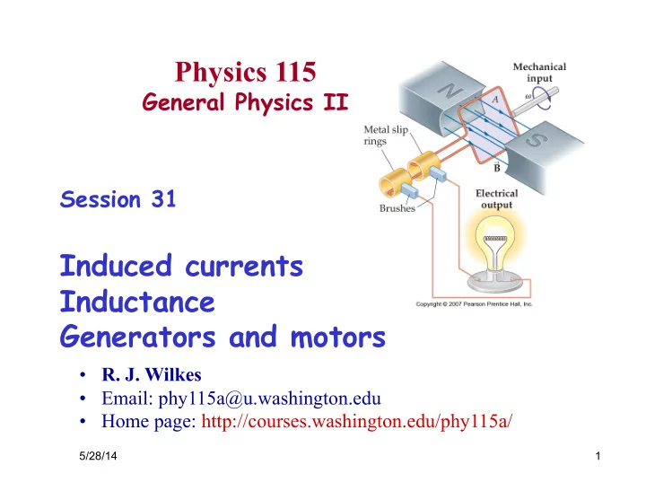
Induced currents Inductance Generators and motors
5/28/14 1
- R. J. Wilkes
- Email: phy115a@u.washington.edu
- Home page: http://courses.washington.edu/phy115a/