
SLIDE 1
Physics 115
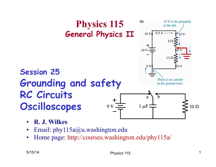
General Physics II Session 25
Grounding and safety RC Circuits Oscilloscopes
5/15/14 1
- R. J. Wilkes
- Email: phy115a@u.washington.edu
- Home page: http://courses.washington.edu/phy115a/
Physics 115