High Energy Density Flow Battery Dr. Grigorii Soloveichik, GE - - PowerPoint PPT Presentation

high energy density flow battery
SMART_READER_LITE
LIVE PREVIEW

High Energy Density Flow Battery Dr. Grigorii Soloveichik, GE - - PowerPoint PPT Presentation

TEAM: High Energy Density Flow Battery Dr. Grigorii Soloveichik, GE (retired) for EV Storage Dr. Sergei Kniajanski, GE Senior Scientist Dr. Guillermo Zappi, GE Senior Scientists Technology Overview Malgorzata Rubinsztajn, Oltea Siclovan GE


slide-1
SLIDE 1

Technology Overview Current Status

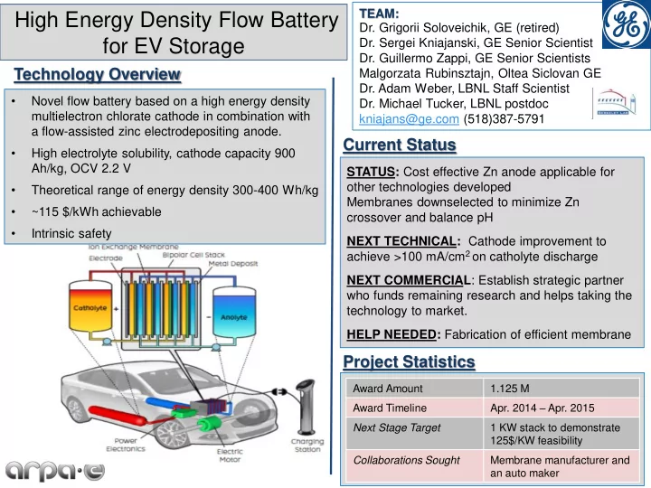
  • Novel flow battery based on a high energy density

multielectron chlorate cathode in combination with a flow-assisted zinc electrodepositing anode.

  • High electrolyte solubility, cathode capacity 900

Ah/kg, OCV 2.2 V

  • Theoretical range of energy density 300-400 Wh/kg
  • ~115 $/kWh achievable
  • Intrinsic safety

STATUS: Cost effective Zn anode applicable for

  • ther technologies developed

Membranes downselected to minimize Zn crossover and balance pH NEXT TECHNICAL: Cathode improvement to achieve >100 mA/cm2 on catholyte discharge NEXT COMMERCIAL: Establish strategic partner who funds remaining research and helps taking the technology to market. HELP NEEDED: Fabrication of efficient membrane

High Energy Density Flow Battery for EV Storage

TEAM:

  • Dr. Grigorii Soloveichik, GE (retired)
  • Dr. Sergei Kniajanski, GE Senior Scientist
  • Dr. Guillermo Zappi, GE Senior Scientists

Malgorzata Rubinsztajn, Oltea Siclovan GE

  • Dr. Adam Weber, LBNL Staff Scientist
  • Dr. Michael Tucker, LBNL postdoc

kniajans@ge.com (518)387-5791

Project Statistics

Award Amount 1.125 M Award Timeline

  • Apr. 2014 – Apr. 2015

Next Stage Target 1 KW stack to demonstrate 125$/KW feasibility Collaborations Sought Membrane manufacturer and an auto maker

slide-2
SLIDE 2

Technology description

Initial challenges

Anode Zn concentration  3 M Corrosion stability in acidic media Zn dense plating vs slurry Cathode Slow discharge kinetics, electrocatalyst Faradaic efficiency Overpotential pH control Membrane High H+ conductivity at low M+ crossover System integration High energy efficiency Cycleability Water balance pH control ClO3

  • + 6 H+ + 6e-  Cl- + 3 H2O

Zn2+ + 2e-  Zn0

GE proprietary, patent pending

slide-3
SLIDE 3

Anolyte development

  • Several buffered, cost effective

anode formulations developed with Zn concentration 2.5-3.5 M at 0% SoC

  • pH well maintained over cycling
  • > 97% Zn deposition efficiency on 150

mA/cm2 charge

  • < 3% Zn non-coulombic loss on 150

mA/cm2 discharge

  • Flat Zn deposition morphology on 150

mA/cm2 charge

  • Demonstrated on 40 cm2 Zn electrode

in a flow cell

  • Efficiency mostly affected by buffer

composition rather than by pH

  • Could be used in other technologies

Electrolyte 1 50 % SoC, 150 mA/cm2 Electrolyte 2 0 % SoC, 500 mA/cm2

Morphology of Zn deposition

slide-4
SLIDE 4

Cathode development

  • Slow kinetics of ClO3
  • to Cl- reduction is

the biggest challenge

  • pH increase is not favorable
  • Chronopotentiometry used for screening

potential catalytically active electrodes and reaction conditions

  • Promising candidates have been

identified

  • Results have recently improved to ~100

mA/cm2 at small scale

  • Electrodes with enhanced surface area

electrode may help in reaching the target

1 2 3 4 5 6 7 8 5 10 15 20 25 6000 7000 8000 9000 10000

pH Current density, mA/cm2 Reaction time, s

pH effect on current density @ 0.5V

Current density Catholyte pH Anolyte pH

Current density on different electrodes

slide-5
SLIDE 5

Membrane Selection

Tradeoff between conductivity and crossover Range of PEM and Microporous overlap Not enough difference for downselection between PEM and Microporous Microporous significantly less expensive

Cost $/m2 Conductivity (mS/cm) ASR (Ohm- cm2) Zn Crossover Rate (mg/h/cm2/M) Daramic Lead-acid separator 4-6 16 1.6 5.4 Millipore PES Filtration 70-200 59 0.2 10.4 NR211 As-received 350-1000 3 0.8 0.03 NR211 Boiled 350-1000 16 0.2 5.5

  • Measured conductivity and crossover for range of PEM and microporous

separators

  • Downselected to NR211, Millipore PES, and Daramic for further testing
slide-6
SLIDE 6

System integration

Flow cell – 82 cm2 membrane area

0.5 1 1.5 2 2.5

  • 1.5
  • 1
  • 0.5

0.5 1 1.5 5000 10000 15000 20000 25000 Voltage(V) Current(A) Test_Time(s)

Current(A), Voltage(V) vs. Test_Time(s)

1-001 Current(A) 1-001 Voltage(V)

20 40 60 80 100 120 0.0 0.2 0.4 0.6 0.8 1.0 1.2 1.4 1.6 1.8 2.0

3M NaClO3 HCl

Current Density (mA/cm

2)

Voltage (V)

Chlorate ca cathode with H2 anode

H2/GDL/Pt-C/NR211/Ti mesh/GDLx3/3M NaClO3 with HCl, no catalyst Performance stable drawing current 40 mA/cm2 at 1.0 V for at least 20 min

Chlorate anode with zinc c anode

  • Chlorine evolution at low pH
  • Shallow cycles demonstrated at

higher pH in developed electrolyte

  • Product analysis underway
  • Deep cycling and pH control to be

demonstrated