SLIDE 1 En Energ ergy y Man Manag ageme ement nt Work Worksh shop
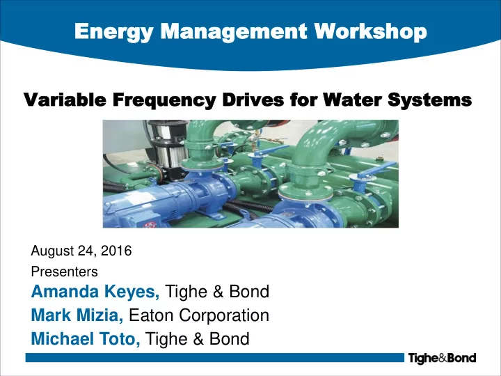
Variable Variable Frequ Frequenc ency y Drives Drives for for Water Water Sy Systems stems
August 24, 2016 Presenters
Amanda Keyes, Tighe & Bond Mark Mizia, Eaton Corporation Michael Toto, Tighe & Bond
SLIDE 2
Ex Example ample VFD VFD Application Application – Concord WT Concord WTP
■ Booster Pump System for Plant Water ■ Problems with system:
– Lack of response control – Pumps oversized – High energy usage per gallon of water pumped
SLIDE 3
Ex Example ample VFD VFD Application Application – Concord WT Concord WTP
Maintain constant discharge pressure under varying demand conditions
SLIDE 4
Pu Pump mp Sp Speed eed 101 101
■ Motor / pump designed to run on pump curve, head added will decrease as flow rate increases ■ At the mercy of the system to determine where you fall on the pump curve ■ If required flow ≠ pump operating point:
1. Cycle pumps on/off 2. Adjust speed
SLIDE 5
Pu Pump mp Curves Curves at at Various Various Sp Speed eeds
SLIDE 6
Flow Adjustment Flow Adjustment Method Methods
SLIDE 7 What doe What does a VFD s a VFD Do? Do?
■ The Cause:
– VFD decreases AC frequency
» Example: 60 Hz 30 Hz
■ The Effect:
– Motor Speed1
» Example: 1200 rpm 600 rpm
– Flow Rate1
» Example: 200 gpm 100 gpm
– Head2
» Example: 100 ft 25 ft
– Horsepower3
2 1 2 1
Flow Flow Speed Speed
2 1 2 1
Speed Speed Frequency Frequency
2 1 3 2 1
Horsepower Horsepower Speed Speed
2 1 2 2 1
Head Head Speed Speed
SLIDE 8 Ex Examp ample of le of VFD VFD Applic Applicatio ation
Pump Speed Flow Rate (gpm) Measured Pump Efficiency kWh/ MG Pumped 50 Hz 1,645 0.72 1,104 54 Hz 1,977 0.76 1,163 60 Hz 2,415 0.73 1,325
- Selecting best speed for well
pump operation to reduce energy costs
- Field Measurements to measure
flow rate, operating power, suction/discharge pressures
*Data collected by JKMuir for Tighe & Bond as part of Southington CT Capital Plan
SLIDE 9
Not Not So So Fas Fast... t...
■ Considerations before adding VFDs:
– Adds installation cost – Adds system complexity – Motor must be compatible (inverter duty rated) – VFDs generate heat and requires cooling and ventilation for proper operation – Process/System limitations – Lack of system controls
SLIDE 10
Variable Variable Sp Speed eed AC AC Dri Drives ves
SLIDE 11 Introduction to VFD’s
■ All ‘good’ drive products should have integral PID algorithm(s) available within the drive logic. ■ That allows the operator to use the drive to regulate flow based on a setpoint (pressure, flow rate, temp etc). If the site does not have a SCADA
- r Control System that is doing the PID
calculation
SLIDE 12 Centrifugal Centrifugal Pu Pumps mps
Typical Pump Applications
– Chilled and Hot water Pumps – Condenser Water Pumps – Booster Pumps Feature
Variable Speed Drive
Benefit
– Variable Flow to Demand – Operating at reduced pressures – Longer pump seal life & reduced impeller wear & less system vibration High Efficiency – Significant savings at reduced flows – Constant volume pumps can be converted to variable volume Soft Start – Reduces in rush current by 5X – Saves on wear of system – Pump can be ramped up to speed vs. going to full GPM
Proportional PID Control from Drive or Controller IntelliPass w/ Bypass Motor Leads BUS or Analog Command
Centrifugal Pump
SLIDE 13
Centrifugal Centrifugal Pu Pump mp
SLIDE 14
En Energy Saving ergy Savings s Report Report Ex Example ample
SLIDE 15
En Energy Saving ergy Savings s Report Report Ex Example ample
SLIDE 16
En Energy Saving ergy Savings s Report Report Ex Example ample
SLIDE 17
Key Ta Key Takea keaways ways
■ Adjustable Frequency Drive Benefits
– Reduce energy consumption – Longer mechanical life – Reduce maintenance – Eliminate power surges during starts and stops – Improve power factor
SLIDE 18
Harmonic Reduction Methods Available
■ Standard 3-5% Impedance Line Reactors on all HVX Drives (Frame Dependent) ■ Optional 5% Line Reactors on Enclosed Drives, N12 Intellipass ■ Options for Integral Passive Harmonic Filters for standard 6 Pulse Drives (TCI or MTE Broadband Filters) ■ CFX Model – Integrates Passive Filter into 6 Pulse VFD Enclosure ■ 12 Pulse VFD Construction (integral or external phase / shift transformer) ■ 18 Pulse Clean Power VFD Construction ■ External Active Filter Products (for use in Motor Control Center Construction) ■ 24 Pulse Medium Voltage Design (2400v & 4160v up to 10,000HP)
SLIDE 19
En Energy Saving ergy Savings s with with Variable Variable Sp Speed eed Dri Drives ves
■ Target Equipment:
– Pumps and Motors – Boiler Equipment – Building Automation Systems – Chillers – Cooling Towers – Compressors – Heat Treating Equipment – Humidification (Dehumidification)
SLIDE 20
VFD VFD Se Selection lection Cri Criteria teria
■ Motor full load amps ■ Motor voltage, RPOM and HP ■ Application (pump, fan, conveyor, grinder, etc.) ■ Variable or Constant Torque (Low or High Overload) ■ Supply voltage and phase ■ Motor voltage ■ Type of enclosure (NEMA 1,12,3R, 4X, MCC) ■ Mounting environment (indoors, outdoors, caustic, wash-down, etc.) ■ VFD Topology Requirements (6 pulse, 18 pulse, 6 pulse with harmonic filter)
SLIDE 21
VFD VFD Se Selection lection Cri Criteria teria (co
(cont nt.) .)
■ Input Line Reactor or DC Choke Required ■ Cable Distance VFD to Motor ■ Control Source (local, remote, PLC, SCADA/BAS) ■ Communications Network Required for Control (Modbus, Ethernet, etc.) ■ Speed Reference Input (analog, transducer, 4-20ma, 0-10Vd) ■ Dynamic Braking Required? ■ Power Options Required (disconnect, bypass, etc.) ■ Cover Control Options (lights, pushbuttons, selector switches, meters…) or is Keypad Operation OK
SLIDE 22 Motor Motor Sta Starting Metho rting Methods ds
■ Across the line, Full Voltage (NEMA, IEC, Definite Purpose) ■ Reduced Voltage (electromechanical, solid-state) ■ Adjustable Frequency Drives
Starter = Contactor + Overload Protection VFD in NEMA 3R Enclosure
SLIDE 23
Introduction to VFD’s
■ Flow control techniques for pumps and fans include throttling or restrictive devices such as
– Valves – Outlet dampers – Inlet vanes – Diffusers – Mechanical speed changers – Recirculation systems
SLIDE 24
Introduction to VFD’s
■ Restrictive Devices Waste Energy and Increase Costs
– Friction and heat – Premature mechanical wear – Require high maintenance – As inefficient as driving a car with the gas pedal to the floor and controlling speed by pressing the brake petal
SLIDE 25
Introduction to VFD’s
■ Variable Frequency Drives eliminate the losses and cost of throttling devices.
– Low cost retrofit to existing motors – Ideal soft starting and stopping – High system efficiency – Noise reduction – Reduce mechanical wear and maintenance – Reduce KW demand