Dry Electropolishing of an Additively Manufactured Spacer Grid - - PDF document

dry electropolishing of an additively manufactured spacer
SMART_READER_LITE
LIVE PREVIEW

Dry Electropolishing of an Additively Manufactured Spacer Grid - - PDF document

Transactions of the Korean Nuclear Society Virtual Spring Meeting July 9-10, 2020 Dry Electropolishing of an Additively Manufactured Spacer Grid Han-Gil Woo , Jin-Seon Kim, Joo-Young Ryu, Jin-Seok Lee, Seung-Jae Lee KEPCO Nuclear Fuel


slide-1
SLIDE 1

Dry Electropolishing of an Additively Manufactured Spacer Grid

Han-Gil Woo∗, Jin-Seon Kim, Joo-Young Ryu, Jin-Seok Lee, Seung-Jae Lee KEPCO Nuclear Fuel Co.,242, Daedeok-daero 989beon-gil, Yuseong-gu, Daejeon, 34057, Republic of Korea

*Corresponding author: hgwoo@knfc.co.kr

  • 1. Introduction

Additive manufacturing, also called as three- dimensional printing, is a technology that build objects by adding many layers of material, whether the material is usually plastic and metal. Over the past few years, KEPCO NF has been putting efforts to seek feasibility

  • f adopting this technology for the manufacturing of

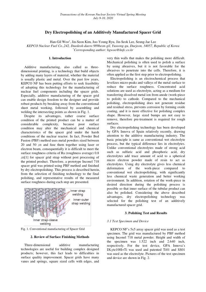
nuclear fuel components including the spacer grids. Especially, additive manufacturing of the spacer grid can enable design freedom to the designer and provide robust products by breaking away from the conventional sheet metal working, followed by assembling and welding the intersecting points as shown in Fig. 1. Despite its advantages, rather coarse surface condition of the printed product can be a matter of considerable complexity, because poor surface condition may alter the mechanical and chemical characteristics of the spacer grid under the harsh conditions of the nuclear reactor. In fact, Powder Bed Fusion (PBF) method uses metal powders sized between 20 and 50 ㎛ and fuse them together using laser or electron beam, consequentially it is difficult to meet the surface roughness criteria of Ra (roughness average) 0.8 ㎛[1] for spacer grid strap without post processing of the printed product. Therefore, a prototype Inconel 718 spacer grid was printed using PBF method and finished by dry electropolishing. This process is described herein, from the selection of finishing technology to the final polishing, and representative results of the measured surface roughness during each step are presented.

  • Fig. 1. Conventional manufacturing of Spacer Grid
  • 2. Review of Surface Finishing Methods

Three-dimensional additive manufacturing technologies are useful for building complex designed products; however, this fact leads to difficulties in surface quality improvement. Spacer grids have many vanes and springs, square sized cells with edges, and very thin walls that makes the polishing more difficult. Mechanical polishing is often used to polish a surface by using abrasives, but it is not favorable for the abrasives to penetrate into the cells. Therefore, it is

  • ften applied as the first step prior to electropolishing.

Electropolishing is an electrochemical process that levelizes micro-peaks and valleys of the metal surface to reduce the surface roughness. Concentrated acid solutions are used as electrolyte, acting as a medium for transferring dissolved metal ion from anode (work-piece to polish) to cathode. Compared to the mechanical polishing, electropolishing does not generate residue and residual stress, prevents corrosion by forming oxide coating, and it is more effective for polishing complex

  • shape. However, large sized bumps are not easy to

remove, therefore pre-treatment is required for rough surfaces. Dry electropolishing technology has been developed by GPA Innova of Spain relatively recently, drawing attention to the additive manufacturing industry. The basic principle is same as conventional wet electrolyte process, but the typical difference lies in electrolytes. Unlike conventional electrolytes made of strong acid such as sulfuric acid and phosphoric acid, dry electrolytes add trace amount of acid to a spherical micro electron powder made of resin to act as

  • electrolytes. Using dry electrolyte gives less chemical

deformation

  • f

the work-piece compared to conventional wet electropolishing, with significantly less chemical waste generation and better working

  • environment. In addition, rotation of the work-piece in

desired direction during the polishing process is possible so that inner surface of the tubular product can also be polished. Considering the above described advantages, dry electropolishing technology was selected for the polishing test of an additively manufactured spacer grid.

  • 3. Polishing Test and Results

3.1 Test Specimen and Device KEPCO NF’s 5x5 array spacer grid was used as a test

  • specimen. The grid was manufactured by PBF method

using Inconel 718 metal powder. Height and width of the specimen was 1.522 inch and 2.640 inch,

  • respectively. For the test device, GPA Innova’s

DLyte100I+Ti was used and patented Ti01 and SS01 was used as the electrolyte. Pictures of the test specimen and device are shown in Fig. 2.

Transactions of the Korean Nuclear Society Virtual Spring Meeting July 9-10, 2020

slide-2
SLIDE 2

(a) Test specimen (b) Test device

  • Fig. 2. Test specimen and device

3.2 Test Procedure In order to achieve a better surface quality, the specimen was abrasive blasted with Al2O3 bids and steam cleaned. The specimen was fixed to the dry electropolishing device and was polished for total 8

  • hours. Surface roughness was measured before and after

the polishing process, and the device was stopped after the 4 hours for measurement. Additionally, one row of the specimen was electric discharge machined to reveal the inner surface for measurement. Each point of measurement is shown in Fig. 3. Key process variables for the device include voltage and polarity as listed in Table 1. To enhance the polishing effect, DLyte repeatedly changes the applied polarity of the work-piece because anode will function as polishing and cathode will remove oxide film on the surface that blocks active polishing.

  • Fig. 3. Point of measurement for outer surface (left) and inner

surface (right) Table 1. Process variables Time Voltage Polarity Sequence First hour 35 volts (+) 100 ㎲ Pause 50 ㎲ (-) 50 ㎲ Pause 50 ㎲ Next 3 hours 40 volts Next 4 hours 25 volts (+) 1 ㎳ Pause 200 ㎳ (-) 1 ㎳ Pause 250 ㎳

3.3 Test Result Visual inspection has shown that large proportion of the layer pattern that was formed during build-up is removed due to the polishing process. It also had a glowing effect on the outside surface with very smooth

  • texture. However, most corner areas did not appear to

have properly removed the bump pattern, and inner surface as well as the spring and dimple surfaces were also found to have not polished as much as the outer surfaces.

  • Fig. 4. Specimen after 4 hours of dry electropolishing (left)

and after 4 additional hours (right)

Surface profile of the specimen was measured using three-dimensional surface measuring instrument. As a result, average Ra of the 3 outer points was reduced from 1.95 ㎛ to 0.39 ㎛ and Rq (root mean square roughness) was reduced from 2.49 ㎛ to 0.47 ㎛. It was also found out that there were no big improvements after re-polishing (additional 4 hours) compared to the measurement results of the first 4 hours. Table 2 and Fig. 5 summarizes the test result of outer surface. Inner surface of the specimen was measured after completing 8 hours of polishing. Average Ra and Rq of the 9 points were 1.34 ㎛ and 1.68 ㎛, respectively. There is no comparison target because the as-built specimen could not have been cut to reveal the inner surface, however improvement of the surface roughness was relatively low compared to the outer surface.

Table 2. Surface roughness measurement result (unit: ㎛) Para meter Condition Point 1 Point 2 Point 3 Avg. Ra (avg.) As-built 1.84 2.29 1.71 1.95 Polishing (4h) 0.43 0.48 0.60 0.50 Re- polishing (4h) 0.31 0.46 0.41 0.39 Rq (avg.) As-built 2.27 2.92 2.27 2.49 Polishing (4h) 0.52 0.58 0.71 0.60 Re- polishing (4h) 0.34 0.55 0.51 0.47 Transactions of the Korean Nuclear Society Virtual Spring Meeting July 9-10, 2020

slide-3
SLIDE 3
  • Fig. 5. Summary of test result
  • 4. Conclusions

A prototype additively manufactured 5x5 Inconel 718 spacer grid was surface finished using dry electropolishing technology. It was found out that Ra of the outer surface was reduced approximately 80 percent compared to the as-built condition, however the inner surface was not reduced as expected. In order to enhance the surface quality of additively manufactured products through dry electropolishing, suitable process variables should be developed depending on the shape and material of the work-piece through repeated tests. The main variables will include voltage, polarity cross time, polishing time, selection of proper jig, and the rotation sequence of the jig during polishing. ACKNOWLEDGEMENTS This work was supported by the Korea Institute of Energy Technology Evaluation and Planning(KETEP) grant funded by the Korea government(MOTIE) (20171510102030, Development of manufacturing technology of nuclear fuel assembly supporting structures and safety class 1 valve items based on 3D printing and standardizations) REFERENCES

[1] ASTM Standard B352/B352M, 2006, “Standard Specification for Zirconium and Zirconium Alloy Sheet, Strip, and Plate for Nuclear Application,” ASTM International, West Conshohocken, PA, 2003, DOI: 10.1520/B0352_B0352M-02R06, www.astm.org. Transactions of the Korean Nuclear Society Virtual Spring Meeting July 9-10, 2020