
SLIDE 1
Digital pulse sensors
William Sandqvist william@kth.se
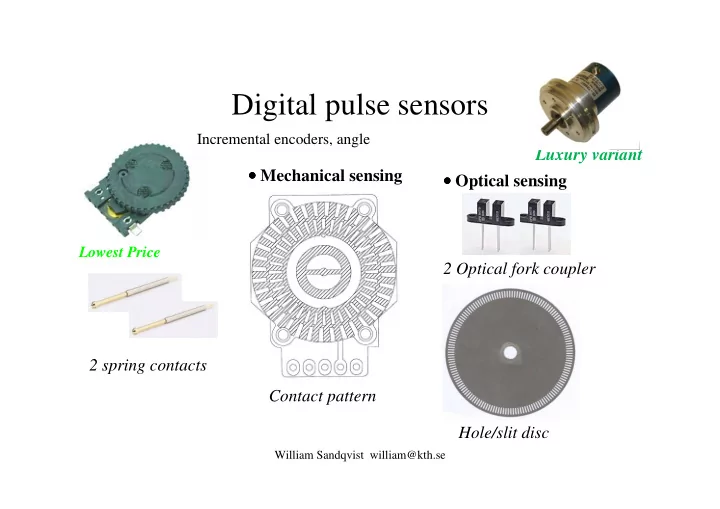
Incremental encoders, angle
Contact pattern Hole/slit disc 2 Optical fork coupler 2 spring contacts
- Optical sensing
- Mechanical sensing
Lågpriskomponenten
Luxury variant
Lowest Price