
SLIDE 1
11/9/2019 1
15-441/641: Physical and Datalink Layers
15-441 Fall 2019 Profs Peter Steenkiste & Justine Sherry Fall 2019 https://computer-networks.github.io/fa19/
Back to Basics
- 1. Physical layer.
- 2. Datalink layer
introduction, framing, error coding, switched networks.
- 3. Contention-based
networks, e.g., ethernet.
Application Presentation Session Transport Network Datalink Physical
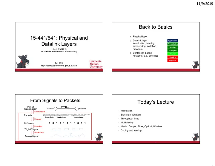
From Signals to Packets
Analog Signal “Digital” Signal Bit Stream
0 0 1 0 1 1 1 0 0 0 1
Packets
0100010101011100101010101011101110000001111010101110101010101101011010111001
Header/Body Header/Body Header/Body
Receiver Sender
Packet Transmission
Modulation Encoding Framing Error control
Today’s Lecture
- Modulation
- Signal propagation
- Throughput limits
- Multiplexing
- Media: Copper, Fiber, Optical, Wireless
- Coding and framing
4