outline
play

Outline Circuit switching refresher Virtual Circuits 15-441/641: - PowerPoint PPT Presentation

11/23/2019 Outline Circuit switching refresher Virtual Circuits 15-441/641: Computer Networks Why virtual circuits? Virtual Circuits, MPLS,VLAN How do they work? Todays virtual circuits: MPLS 15-441 Fall 2019 Profs


  1. 11/23/2019 Outline • Circuit switching refresher • Virtual Circuits 15-441/641: Computer Networks Why virtual circuits? • Virtual Circuits, MPLS,VLAN How do they work? • • Today’s virtual circuits: MPLS 15-441 Fall 2019 Profs Peter Steenkiste & Justine Sherry • Virtual LANs How do they differ? • Fall 2019 https://computer-networks.github.io/fa19/ Circuit Switching Circuit Switching • Source first establishes a connection (circuit) to • Switches remembers how to forward the destination. Switch data Each router or switch along the way may reserve some • bandwidth for the data flow • No packets or addresses! • Source sends the data over the circuit. No destination address needed - routers know the path • Many options for switches • • The connection is torn down. • Connect specific wires (circuit = wire) • Example: traditional telephone network.
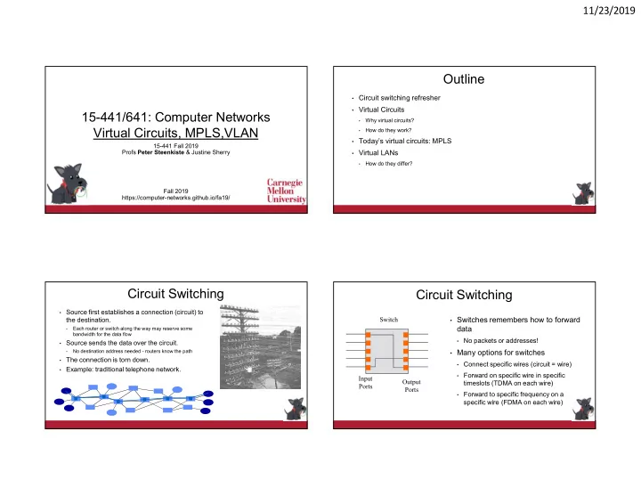
 • Forward on specific wire in specific Input Output timeslots (TDMA on each wire) Ports Ports • Forward to specific frequency on a specific wire (FDMA on each wire) 1

  2. 11/23/2019 Virtual Circuits Circuit Versus Packet Switching Each wire carries many “virtual” circuits • Circuit Switching Packet Switching Forwarding based on virtual circuit (VC) identifier in a packet header • • Fast switches can be built • Switch design is more IP header: source IP, destination IP, etc. • relatively inexpensively complex and expensive Virtual circuit header: VC ID, .. • • Inefficient for bursty data • Allows statistical A path through the network is set up when the VC is established • multiplexing Statistical multiplexing for efficiency, similar to IP • • Predictable performance Can support wide range of quality of service • (e.g. hard QoS) • Difficult to provide QoS No guarantees: best effort service guarantees • • Requires circuit Weak guarantees: delay < 300 msec, … • establishment before • Data can be sent without Strong guarantees: e.g. equivalent of physical circuit • communication signaling delay and overhead Can we get the benefits of both? Virtual Circuits Versus Virtual Circuit Forwarding Packet Switching A Switch C VC1 Many similarities: • 1 Forwarding based on “address” (VCID or destination address) • 3 B 2 VC2 D 4 Statistical multiplexing for efficiency • VC3 Must have buffers space on switches • F E Virtual circuit switching: • Address Next Hop Uses short connection identifiers to forward packets • • The address used for look up in the forwarding Switches maintain state for each connection so they can more easily implement features such VC1 3 • as quality of service table is a virtual circuit identifier (VC id) VC2 3 Switches are stateful: VC connection state cannot be lost • • Forwarding table entries are filled in during VC3 4 Packet switching: • signaling Uses full destination addresses for forwarding packets VC4 ? • • VC id is often shorter than destination address Can send data right away: no need to establish a connection first • VC5 ? and is typically “flat” (e.g., no CIDR) Switches are stateless: easier to recover from failures • Adding QoS is hard, kind of – see QoS lecture • 2

  3. 11/23/2019 VC versus Packets: How to Pick a New VC Id? Control over the End-to-End Path A Switch C VC1 = 1 Payload 1 VCI Payload Dst B 3 2 VC2 = 2 D 4 VC3 = 3 F 1 3 A E R2 Different paths to 2 1 3 4 1 3 same destination! R1 R4 Dst • When B establishes green virtual circuit, how does it know 2 4 (useful for traffic 2 4 1 3 B R3 what VC ids are available at all hops along the path? engineering!) 2 4 • Even worse: every VC id may already be used on a link along R1 VC table: R1 packet the path to the destination! forwarding table: VC 1 R2 • Solution: VC id swapping Dst R2 VC 2 R3 Connections and Signaling VC id Swapping • Permanent vs. switched virtual connections (PVC/SVC) A 1 Switch 1 C VC1 2 1 static vs. dynamic. PVCs last “a long time” • 2 2 1 3 1 E.g., connect two bank locations with a PVC B 3 • 2 VC2 D 1 2 4 2 1 SVCs are more like a phone call • VC3 2 F PVCs administratively configured (but not “manually”) E • 3 SVCs dynamically set up on a “per-call” basis • • Topology Address Next Hop Next id • Look up is based on VC id in header + incoming port number point to point, point to multipoint, multipoint to multipoint VC1 = 1 3 2 • • Challenges: How to configure these things? • Forwarding table specifies VC2 = 2 3 3 outgoing port and new VC id What VCI to use? VC3 = 1 4 1 • • VC id conflicts can be resolved Setting up the path • VC4 = 2 3 1 locally during signaling 3

  4. 11/23/2019 Basic SVC Connection Setup Virtual Circuits In Practice • Asynchronous Transfer Mode - ATM: Teleco approach calling network called Based on 53 byte “cells”, not packets (I am not kidding) • party party Kitchen sink: design driven by voice requirements, but supports file transfer, • video, etc., SETUP Intended as IP replacement. That didn’t happen. :) • Today: dead. • SETUP • MPLS: The “IP Heads” answer to ATM CONNECT Stole all the good ideas from ATM and integrated them into IP • Today: Used inside many transit networks to provide traffic engineering, VPN • support, .. CONNECT • Other networks just run IP. CONNECT • Older (ancient?) technology: Frame Relay ACK Only provided PVCs. Used for quasi-dedicated 56k/T1 links between offices, CONNECT • ACK etc. Slower, less flexible than ATM. Outline MPLS • Circuit switching refresher • Multi-Protocol Label Switching Layer 3 (IP) header • Virtual Circuits • Brings the virtual circuit concept into IP Layer 2 header • Driven by multiple forces Why virtual circuits? • QoS, traffic engineering • How do they work? • Simplifies packet forwarding • • Today’s virtual circuits: MPLS Layer 3 (IP) header • MPLS is implemented using an MPLS that sits • Virtual LANs between the IP and datalink header MPLS label VC ID is called an MPLS label How do they differ? • • Layer 2 header Some MPLS slides from H. Zhang 4

  5. 11/23/2019 Label Switched Router (LSR) Label Switched Paths (LSP) • Performs LSP setup and MPLS packet forwarding • Uni-directional path between two routers in an ISP’s network • Label Edge Router (LER): LSP ingress or egress • Forces packet along a specific path (set of routers) • Transit Router: forwards packet and swaps MPLS label New York Ingress New York San San Francisco Egress Francisco Transit MPLS Header MPLS Header • IP packet is encapsulated in MPLS header by the LSP ingress router and sent down a LSP Label CoS S TTL IP Packet • Label – 20 bits that identify LSP • Class of service 32-bit MPLS Header • Stacking bit Packets can be encapsulated in multiple MPLS headers • MPLS forward packet based on the label • • Time to live • IP packet is restored at end of LSP by egress router Decrement at each LSR, or • • TTL is adjusted, transit LSP routers count towards the TTL Pass through unchanged • • MPLS is an optimization – it does not affect IP semantics 5

  6. 11/23/2019 Forwarding Equivalence Classes Establishing LSPs • Use the Label Distribution Protocol (LDP) to establish paths LSR LSR LER LER based on IP forwarding tables LSP • Simple: IP routing protocols map forwarding of IP prefixes to IP1 IP1 LSPs as they fill in IP forwarding tables IP1 #L1 IP1 #L2 IP1 #L3 • Establish new LSPs as needed IP2 #L1 IP2 #L2 IP2 #L3 • MPLS packets follow the same path as IP – lose some MPLS IP2 IP2 benefits Packets are destined for different address prefixes, but can be • Explicitly establish LSPs to control flow of traffic mapped to common path • More work • FEC = “A subset of packets that are all treated the same way by a LSR” • Provides finer grain control over how traffic is distributed • The concept of FECs provides for a great deal of flexibility and scalability throughout the network • Can be used to force flows of different “sizes” (e.g., Mbps) to follow certain • Important tool for traffic engineering paths through the network – more flexible than traditional routing LSPs Driven by IP Routing MPLS Builds on Standard IP D e s t O u t 4 7 . 1 1 #216 D e s t O u t 4 7 . 2 2 #14 #311 4 7 . 1 1 4 7 . 3 3 4 7 . 2 2 #99 #311 4 7 . 3 3 1 47.1 #963 #311 1 2 3 D e s t O u t #963 2 4 7 .1 1 4 7 .2 2 #14 4 7 .3 3 1 #462 #612 47.2 3 47.3 #311 2 #5 #99 - A LSP is actually part of a sink tree with paths from every source to a destination (unidirectional). - A control protocol (e.g. Label Distribution Protocol, LDP) builds the tree based on the IP forwarding tables. • Destination based forwarding tables as built by OSPF, IS-IS, RIP, etc. 6

Download Presentation
Download Policy: The content available on the website is offered to you 'AS IS' for your personal information and use only. It cannot be commercialized, licensed, or distributed on other websites without prior consent from the author. To download a presentation, simply click this link. If you encounter any difficulties during the download process, it's possible that the publisher has removed the file from their server.

Recommend


More recommend