
SLIDE 1
ATM*
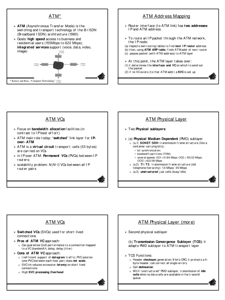
ATM (Asynchronous Transf er Mode) is t he
swit ching and t ransport t echnology of t he B-I SDN (Broadband I SDN) archit ect ure (1980)
Goals: high speed access t o business and
resident ial users (155Mbps t o 622 Mbps); integrated services support (voice, dat a, video, image)
* Kurose and Ross, “Computer Networking”
ATM VCs
Focus on bandwidth allocationf acilit ies (in
cont rast t o I P best ef f ort )
ATM main role t oday: “switched” link layer f or I P-
- ver- ATM
ATM is a virtual circuit t ransport : cells (53 byt es)
are carried on VCs
in I P
- ver ATM: P
ermanent VCs (P VCs) bet ween I P rout ers;
scalabilit y problem: N(N-1) VCs bet ween all I P
rout er pairs
ATM VCs
Switched VCs (SVCs) used f or short lived
connect ions
Pros of ATM VCapproach:
- Can guarant ee QoS perf ormance t o a connect ion mapped
t o a VC (bandwidt h, delay, delay j it t er) Cons of ATM VCapproach:
- I nef f icient support of datagram t raf f ic; P
VC solut ion (one P VC bet ween each host pair) does not scale;
- SVC int roduces excessive latency on short lived
connect ions
- High SVC processing Overhead
ATM Address Mapping
Rout er int erf ace (t o ATM link) has two addresses:
I P and ATM address.
To rout e an I P
packet t hrough t he ATM net work, t he I P node:
(a) inspect s own rout ing t ables t o f ind next I P router address (b) t hen, using ATM ARP table, f inds ATM addr of next rout er (c) passes packet (wit h ATM address) t o ATM layer At t his point , t he ATM layer t akes over: (1) it det ermines t he interf ace and VCon which t o send out t he packet (2) if no VC exist s (t o t hat ATM addr) a SVCis set up
ATM Physical Layer
Two Physical sublayers: (a) Physical Medium Dependent (PMD) sublayer
- (a.1) SONET/ SDH: t ransmission f rame st ruct ure (like a
cont ainer carrying bit s);
- bit synchronizat ion;
- bandwidt h part it ions (TDM);
- several speeds: OC1 = 51.84 Mbps; OC3 = 155.52 Mbps;
OC12 = 622.08 Mbps
- (a.2) TI / T3: t ransmission f rame st ruct ure (old
t elephone hierarchy): 1.5 Mbps/ 45 Mbps
- (a.3) unstructured: j ust cells (busy/ idle)
ATM Physical Layer (more)
Second physical sublayer
(b) Transmission Convergence Sublayer (TCS): it adapt s P MD sublayer t o ATM t ransport layer
TCS Funct ions:
- Header checksum generat ion: 8 bit s CRC; it prot ect s a 4-
byt e header; can correct all single errors.
- Cell delineation
- Wit h “unst ruct ured” P