
SLIDE 1
1
Texture and other Mappings
Texture Mapping Bump Mapping Displacement Mapping Environment Mapping Texture Mapping Bump Mapping Displacement Mapping Environment Mapping
Angel Chapter 7
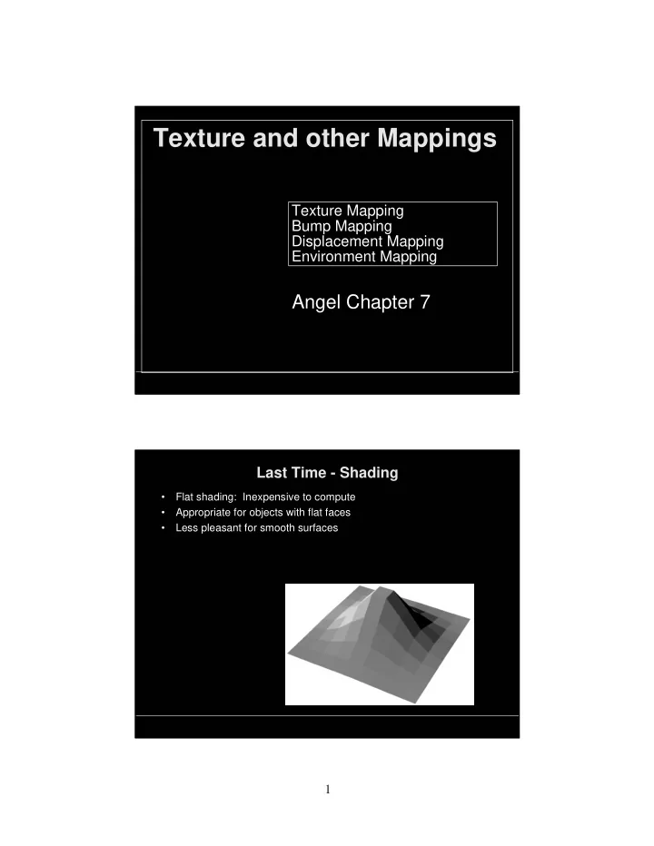
Last Time - Shading
- Flat shading: Inexpensive to compute
- Appropriate for objects with flat faces
- Less pleasant for smooth surfaces