
SLIDE 1
1
Texture and other Mappings
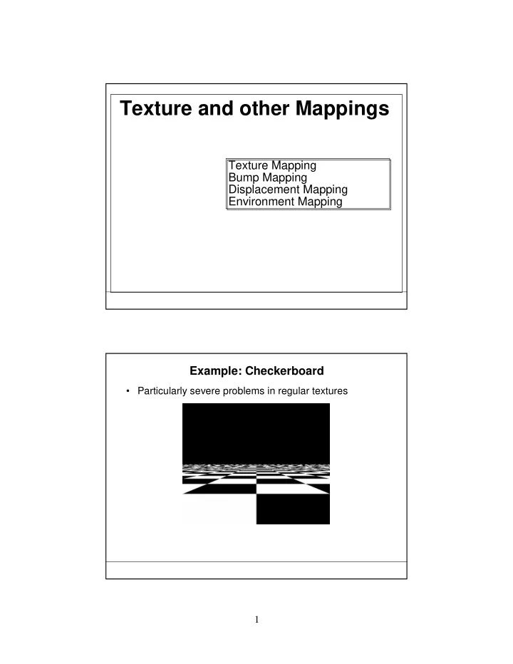
Texture Mapping Bump Mapping Displacement Mapping Environment Mapping Example: Checkerboard
- Particularly severe problems in regular textures
Texture and other Mappings Texture Mapping Bump Mapping - - PDF document
Texture and other Mappings Texture Mapping Bump Mapping Displacement Mapping Environment Mapping Example: Checkerboard Particularly severe problems in regular textures 1 The Beginnings of a Solution: Mipmapping Pre-calculate how
use the appropriate texture at each distance. This is called mipmapping.
– Basic filtering methods assume that a pixel on-screen maps to a square (isotropic) region of the texture – For surfaces tilted away from the viewer, this is not the case!
Figure 5. Anisotropic footprints are very common.
Image courtesy of nVidia
ID Software
ID Software
ID Software
nVidia
(Catmull 1974)
Texture specifies (isotropic) radiance for each point on surface
Sphere w/ Uniform Diffuse coefficient Radiance Map Sphere w/ Radiance Map
Texture specifies diffuse color (kd coefficients) for each point on surface
Sphere w/ Uniform Diffuse coefficient Reflectance (kd) Map Sphere w/ Reflectance Map
any actual change to the shape.
– Option 1: model the surface with many small polygons – Option 2: perturb the normal vectors before the shading calculation
Sphere w/Diffuse Texture Map Bump Map Sphere w/Diffuse Texture + Bump Map
Real Bump Fake Bump Flat Plane
Original model (5M) Simplified (500) Simple model with bump map
Greg Turk
Cylinder w/Diffuse Texture Map Bump Map
– Texture value gives amount to move in direction normal to surface
Glubyte my_texels[512][512][3]; Gluint texID; glGenTextures(1, &texID); glBindTexture(GL_TEXTURE_2D, texID); glTexImage2D(GL_TEXTURE_2D, 0, GL_RGB, 512, 512, 0, GL_RGB,GL_UNSIGNED_BYTE, my_texels); /* level, components, w, h, border, format, type, tarray */ /* assign texture coordinates */ glEnable(GL_TEXTURE_2D); glBegin(GL_QUAD); glTexCoord2f(0.0, 0.0); glVertex3f(x1,y1,z1); glTexCoord2f(1.0, 0.0); glVertex3f(x2,y2,z2); glTexCoord2f(1.0,1.0); glVertex3f(x3,y3,z3); glTexCoord2f(0.0,1.0); glVertex3f(x4,y4,z4); glEnd(); glDisable(GL_TEXTURE_2D);
glTexParameter because many textures are carefully designed to repeat
average nearest 2x2 texels using GL_LINEAR
32x32,16x16,8x8,4x4,2x2 and 1x1 arrays with gluBuild2Dmipmaps
block of marble)
– Use a function [xyz] -> [RGB] to map colors to points in space
procedurally
– No need to store an entire 3D array of colors – Just define a function to generate a color for each 3D point
random ones
– a great marble algorithm has now become cliché
coordinates - otherwise moving the object changes its texture!
From: An Image Synthesizer by Ken Perlin, SIGGRAPH '85