Outline Encoding Bits to digital signal 15-441/641: Datalink - - PowerPoint PPT Presentation

outline
SMART_READER_LITE
LIVE PREVIEW

Outline Encoding Bits to digital signal 15-441/641: Datalink - - PowerPoint PPT Presentation

11/13/2019 Outline Encoding Bits to digital signal 15-441/641: Datalink Framing Bit stream to packets 15-441 Fall 2019 Packet loss & corruption Profs Peter Steenkiste & Justine Sherry Error detection and recovery


slide-1
SLIDE 1

11/13/2019 1

15-441/641: Datalink

15-441 Fall 2019 Profs Peter Steenkiste & Justine Sherry Fall 2019 https://computer-networks.github.io/fa19/

Outline

  • Encoding
  • Bits to digital signal
  • Framing
  • Bit stream to packets
  • Packet loss & corruption
  • Error detection and recovery
  • Flow control
  • Loss recovery

Error Coding

  • Transmission may introduce errors into a message.
  • Received “digital signal” is different from that transmitted
  • Single bit errors versus burst errors
  • Detection:
  • Requires a convention that some messages are invalid
  • Hence requires extra bits
  • An (n,k) code has codewords of n bits with k data bits and r = (n-k) redundant

check bits

  • Correction
  • Forward error correction: many related code words map to the same data word
  • Detect errors and retry transmission
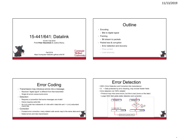
Error Detection

  • EDC= Error Detection and Correction bits (redundancy)
  • D = Data protected by error checking, may include header fields
  • Error detection not 100% reliable!
  • Protocol may miss some errors, but this is rare (more on this later)
  • Larger EDC field yields better detection and correction
slide-2
SLIDE 2

11/13/2019 2

Parity Checking

Single Bit Parity:

Detect single bit errors

6

Internet Checksum

Sender

  • Treat segment contents as

sequence of 16-bit integers

  • Checksum: addition (1’s

complement sum) of segment contents

  • Sender puts checksum

value into checksum field in header

Receiver

  • Compute checksum of

received segment

  • Check if computed checksum

equals checksum field value:

  • NO - error detected
  • YES - no error detected.

But maybe errors nonethless?

  • Goal: detect “errors” (e.g., flipped bits) in transmitted segment
  • Must be easy to computer in software

Cyclic Redundancy Codes (CRC)

  • Widely used codes that have good error detection properties.
  • Can catch many error combinations with a small number of

redundant bits

  • Based on division of polynomials.
  • Errors can be viewed as adding terms to the polynomial
  • Should be unlikely that the division will still work
  • Can be implemented very efficiently in hardware
  • Examples:
  • CRC-32: Ethernet
  • CRC-8, CRC-10, CRC-32: ATM

Basic Concept: Hamming Distance

  • Hamming distance of two bit strings =

number of bit positions in which they differ.

  • If the valid words of a code have

minimum Hamming distance D, then D- 1 bit errors can be detected.

  • If the valid words of a code have

minimum Hamming distance D, then [(D-1)/2] bit errors can be corrected.

1 0 1 1 0 1 1 0 1 0 HD=2 HD=3

slide-3
SLIDE 3

11/13/2019 3 Error Correcting Codes

  • More aggressive coding can allow the receiver to (locally) recover

from errors – Forward Error Correction (FEC)

  • Details outside of scope
  • Informally: if a received code is close to one “red” dot, and far away

from all other “red” dots, it is very likely the nearby red dot

  • With very high probability
  • FEC is very widely used in wireless networks
  • Bit errors are much more common
  • Example: Hybrid ARQ (HARQ) combines ARQ and FEC used in LTE
  • ARQ – automatic repeat request

Take-away: Encoding and Modulation

  • Encoding and modulation work together
  • Must generate a signal that works well for the receiver – has good electrical

properties

  • Must be efficient with respect to spectrum use
  • Can shift some of the burden between the two layers
  • Tradeoff is figured out by electrical engineers
  • Maintaining good electrical properties
  • Spectrum efficient modulation requires more encoding
  • For example: 4B/5B encoding
  • Error recovery
  • Aggressive modulation needs stronger coding

What is Used in Practice?

  • No flow or error control.
  • E.g. regular Ethernet, just uses CRC for error detection
  • Flow control only
  • E.g. Gigabit Ethernet
  • Flow and error control.
  • E.g. X.25 (older connection-based service at 64 Kbs that

guarantees reliable in order delivery of data)

  • Flow and error control solutions also used in higher layer protocols
  • E.g., TCP for end-to-end flow and error control

Outline

  • Datalink architectures
  • Ethernet
  • Wireless networking
  • Wireless Ethernet
  • Aloha
  • 802.11 family
  • Cellular

14

slide-4
SLIDE 4

11/13/2019 4

Datalink MAC Architectures

  • Media Access control (MAC): who

gets to send packet next?

  • Switches connected by point-to-point

links -- store-and-forward.

  • Used in WAN, LAN, and for home connections
  • Conceptually similar to “routing”
  • But at the datalink instead of network layer
  • Multiple access networks.
  • Multiple hosts are sharing the same

transmission medium

  • Used in LANs and wireless
  • Access control is distributed and much more

complex

Datalink Classification

Datalink Switch-based Multiple Access Random Access Scheduled Access Packet Switching Virtual Circuits ATM, framerelay Ethernet, 802.11, Aloha Cellular, FDDI, 802.11 Switched LANs

Scheduled Access MACs

  • Reservation systems
  • Central controller
  • Distributed algorithm, e.g. using

reservation bits in frame

  • Polling: controller polls each nodes
  • Token ring: token travels around ring

and allows nodes to send one packet

  • Distributer version of polling
  • FDDI, …

18

Central Controller

1 2 4 2

3 2 1 4

Random Access Protocols

  • When node has packet to send
  • Transmit at full channel data rate R
  • No a priori coordination among nodes
  • Two or more transmitting nodes  “collision”
  • Random access MAC protocol specifies:
  • How to detect collisions
  • How to recover from collisions (e.g., via delayed retransmissions)
  • Examples of random access MAC protocols:
  • CSMA and CSMA/CD
  • Wireless protocols

19

slide-5
SLIDE 5

11/13/2019 5

Problem: Sharing a Wire

  • Just send a packet when you are ready
  • Does not work well: many collisions! More on this later
  • Natural scheme – listen before you talk …
  • Works well in practice
  • A cheap form of coordination
  • But sometimes this breaks down
  • Why? How do we fix/prevent this?

20

yak yak…

A C B D E

Ethernet MAC Features – CSMA/CD

  • Carrier Sense: listen before you talk
  • Cheap way avoiding collision with active transmission
  • Assumes all nodes can hear each other
  • Collision Detection during transmission
  • Listen while transmitting
  • If you notice interference  assume collision
  • Abort transmission immediately – saves time, reduces penalty
  • f a collision
  • Means a sender can identify competing transmissions while

transmitting

21

Ethernet MAC – CSMA/CD

  • Carrier Sense Multiple Access/Collision Detection

22

Packet? Sense Carrier Discard Packet Send Detect Collision Jam channel b=CalcBackoff(); wait(b); attempts++; No Yes attempts < 16 attempts == 16

Collision Detection: Depends on Packet Length

  • Packets must be long enough to

guarantee all nodes observe collision

  • In this example:
  • A can decode packets
  • C observes collision
  • B and D cannot sense collision
  • Rule: Min packet length > 2x max

prop delay

25

slide-6
SLIDE 6

11/13/2019 6

Collision Detection: Depends on the Wire Length

  • Wires must be short enough to

guarantee all nodes observe collision

  • In this example
  • B and C will see collision
  • A and D cannot see collision
  • Min packet length > 2x max prop

delay

26

Scaling Ethernet

  • What about scaling? 10Mbps, 100Mbps, 1Gbps, ...
  • Oops: packets get shorter (in time – msec)
  • Use a combination of reducing network diameter and increasing minimum minimum

packet size

  • Reality check: 40 Gbps is 4000 times 10 Mbps
  • 10 Mbps: 2.5 km and 64 bytes -> silly
  • Solution: switched Ethernet – see early lecture
  • What about a maximum packet size?
  • Needed to prevent node from hogging the network
  • 1500 bytes in Ethernet = 1.2 msec on original Ethernet
  • For 40 Gps -> 0.3 microsec -> silly and inefficient

28

Things to Remember

  • Trends from CSMA networks to switched networks
  • Need for more capacity
  • Low cost and higher line rate
  • Emphasis on low configuration and management complexity and cost
  • Fully distributed path selection
  • Trends are towards “Software Defined Networks”
  • Network is managed by a centralized controller
  • Allows for the implementation of richer policies
  • Easier to manage centrally
  • Already common in data centers

29

Outline

  • Ethernet
  • Wireless networking intro
  • Spectrum discussion
  • Wireless Ethernet
  • Aloha

30

slide-7
SLIDE 7

11/13/2019 7

History

  • Aloha wireless data network
  • Car phones
  • Big and heavy “portable” phones
  • Limited battery life time
  • But introduced people to “mobile networking”
  • Later turned into truly portable cell phones
  • Wireless LANs
  • Originally in the 900 MHz band
  • Later evolved into the 802.11 standard
  • Later joined by the 802.15 and 802.16 standards
  • Cellular data networking
  • Data networking over the cell phone
  • Many standards – throughput is the challenge

Spectrum Allocation in US

32

Spectrum Use Comments

  • Each country is in charge of spectrum allocation and use

internally

  • Federal Communication Commission (FCC) and National

Telecommunication and Information Administration in the US

  • Spectrum allocation differs quite a bit – implications for mobile users?
  • Broadly speaking two types of spectrum
  • Licensed spectrum: allocated to licensed user(s)
  • Unlicensed spectrum: no license needed but device must respect rules

33

Wireless Communication

  • Wireless communication is based
  • n broadcast
  • A, B, and C can all hear each
  • ther’s signal
  • Looks like Ethernet!
  • Why not use CSMA/CD?
  • Carrier-sense Multiple Access /

Collision Detection

  • Well, it is not that easy

A C B D E A B C D E

slide-8
SLIDE 8

11/13/2019 8 What is the Problem? There are no Wires!

  • Attenuation is very high!
  • Signal is not contained in a wire
  • Attenuation is 1/D2 for distance D
  • There is significant noise and interference
  • No wire to protect the signal
  • Much higher error rates

35

A C B D E A C B D E

  • Not all nodes in the wireless network can hear each other
  • Wireless communication range is shorter
  • Standard cannot limit the length of the wires

Implications for Wireless Ethernet

  • Collision detection is not practical
  • Ratio of transmitted signal power to received power is very high high

at the transmitter

  • Transmitter cannot detect competing transmitters (deaf while

transmitting)

  • So how do you detect collisions?
  • Not all nodes can hear each other
  • “Listen before you talk” often fails
  • Hidden terminals
  • Exposed terminals,
  • Made worse by fading
  • Changes over time!

Hidden Terminal Problem

  • Lack signal between S1 and S2 and cause collision at R1
  • Severity of the problem depends on the sensitivity of the

carrier sense mechanism

  • Clear Channel Assessment (CCA) threshold

S1 S2 R1 R2

Exposed Terminal Problem

  • Carrier sense prevents two senders from sending simultaneously

although they do not reach each other’s receiver

  • Severity again depends on CCA threshold
  • Higher CCA reduces occurrence of exposed terminals, but can create hidden terminal

scenarios

S1 R1 R2 S2

slide-9
SLIDE 9

11/13/2019 9 Aloha – Basic Technique

  • First random MAC developed
  • For radio-based communication in Hawaii (1970)
  • Basic idea:
  • When ready, transmit
  • Receivers send ACK for data
  • Detect collisions by timing out for ACK
  • Recover from collision by trying after random delay

39

Collisions in ALOHA

  • Original ALOHA had no synchronization
  • Pkt needs transmission:
  • Send without awaiting for beginning of slot
  • Many chances for collision
  • Pkt sent at t0 collide with other pkts sent in [t0-1, t0+1]

40

Slotted Aloha

  • Time is divided into equal size slots
  • Equal to packet transmission time
  • Node (w/ packet) transmits at beginning of next slot
  • If collision: retransmit pkt in future slots with

probability p, until successful

41

Success (S), Collision (C), Empty (E) slots

Aloha Throughput Comparison

  • It is possible to calculate throughput for Aloha
  • Many assumptions: exponential arrival, transmitters independent, …
  • Bad news: maximum throughput is low
  • Slotted Aloha can achieve higher throughput
  • Still useful for some networks, e.g., low power, low load, ..

42

G = offered load = N X p

0.5 1.0 1.5 2.0 0.1 0.2 0.3 0.4

Pure Aloha Slotted Aloha

protocol constrains effective channel throughput!