14 332 231 digital logic design
play

14:332:231 DIGITAL LOGIC DESIGN Ivan Marsic, Rutgers University - PDF document

14:332:231 DIGITAL LOGIC DESIGN Ivan Marsic, Rutgers University Electrical & Computer Engineering Fall 2013 Lecture #22: Introduction to Verilog Hardware Description Languages Structural example: Basic idea: Language


  1. 14:332:231 DIGITAL LOGIC DESIGN Ivan Marsic, Rutgers University Electrical & Computer Engineering Fall 2013 Lecture #22: Introduction to Verilog Hardware Description Languages  
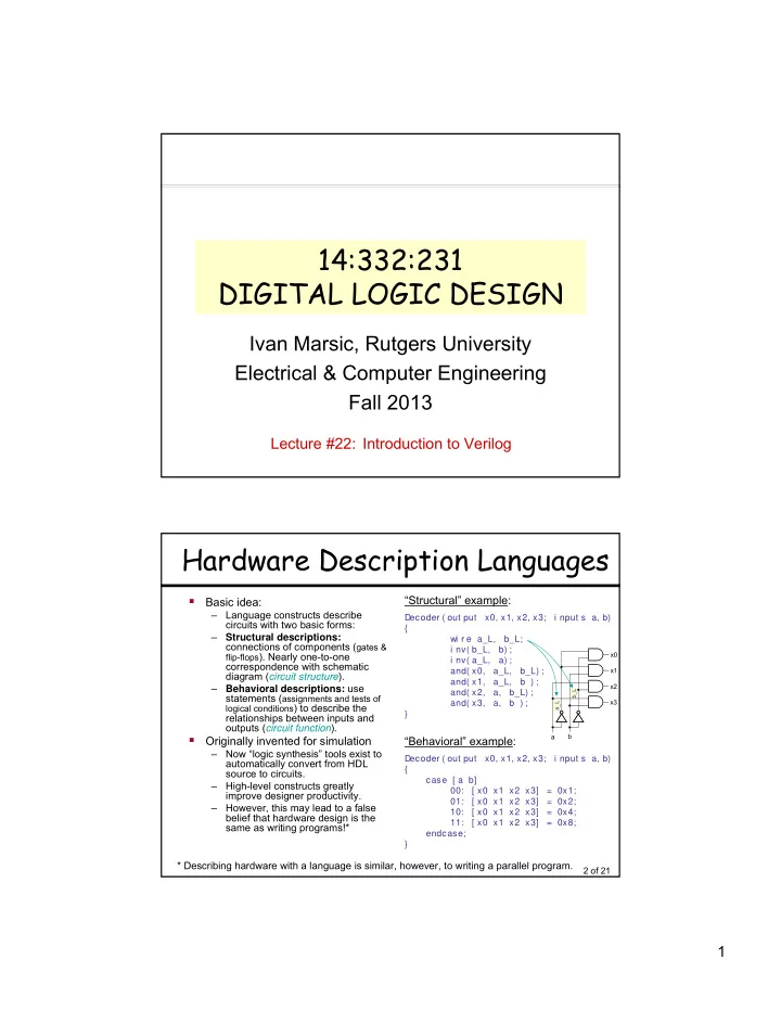
“Structural” example: Basic idea: – Language constructs describe Decoder ( out put x0, x1, x2, x3; i nput s a, b) circuits with two basic forms: { – Structural descriptions: wi r e a_L, b_L; connections of components ( gates & i nv( b_L, b) ; flip-flops ). Nearly one-to-one x0 i nv( a_L, a) ; correspondence with schematic and( x0, a_L, b_L) ; x1 diagram ( circuit structure ). and( x1, a_L, b ) ; x2 – Behavioral descriptions: use and( x2, a, b_L) ; b_L statements ( assignments and tests of and( x3, a, b ) ; x3 a_L logical conditions ) to describe the } relationships between inputs and outputs ( circuit function ).  a b Originally invented for simulation “Behavioral” example: – Now “logic synthesis” tools exist to Decoder ( out put x0, x1, x2, x3; i nput s a, b) automatically convert from HDL { source to circuits. case [ a b] – High-level constructs greatly 00: [ x0 x1 x2 x3] = 0x1; improve designer productivity. 01: [ x0 x1 x2 x3] = 0x2; – However, this may lead to a false 10: [ x0 x1 x2 x3] = 0x4; belief that hardware design is the 11: [ x0 x1 x2 x3] = 0x8; same as writing programs!* endcase; } * Describing hardware with a language is similar, however, to writing a parallel program. 2 of 21 1

  2. Sample Design Methodology Hierarchically defines structure HDL and/or function of circuit. Specification Simulation Synthesis Verification: Checks if the Maps specification to resources design behaves as required of the implementation platform with regards to function, timing, (FPGA or custom silicon). and power consumption. 3 of 21 Top-Down Architecture (1)  Top Down Refinement Process  Start Here: Inputs Project Outputs 4 of 21 2

  3. Top-Down Architecture (2)  End Here: 5 of 21 History of the Verilog HDL  1984: Gateway Design Automation introduced Verilog-XL – digital logic simulator – The Verilog language was part of the Verilog-XL simulator – The language was mostly created by 1 person, Phil Moorby – The language was intended to be used with only 1 product  1989: Gateway merged into Cadence Design Systems  1990: Cadence made the Verilog HDL public domain  1995: The IEEE standardized the Verilog HDL (IEEE 1364)  2001: The IEEE enhanced the Verilog HDL for modeling scalable designs, deep sub-micron accuracy, etc.  2005: The IEEE added minor corrections, spec clarifications, and a few new language features  2009: The IEEE standardized SystemVerilog, with many new features and capabilities to aid design verification and design modeling 6 of 21 3

  4. Verilog Introduction  A m odul e definition describes a component in a circuit  Two ways to describe module contents: – Structural Verilog • Lists sub-components and how they are connected • Just like schematics, but using text • Tedious to write, hard to understand • You get precise control over circuit details • May be necessary to map to special resources of the FPGA – Behavioral Verilog • Describes what a component does, not how it does it • Synthesized into a circuit that has this behavior • Result is only as good as the tools  Build up a hierarchy of modules. Top-level module is your entire design (or the test environment for your design). 7 of 21 Verilog Modules ■ Verilog modules are the building blocks for Verilog designs module module A declarations declarations statements statements ■ One module module B module C module D declarations declarations declarations statements statements statements ■ Modules instantiating module E module F other modules hierarchically declarations declarations statements statements 8 of 21 4

  5. Contents of a Verilog Module  Modules may represent: – An entire design – Major hierarchical blocks within a design m odul e nam e ( por t s ) ; – Individual components within a design por t decl ar at i ons  Modules are completely self dat a t ype decl ar at i ons contained f unct i onal i t y – The only things “global” in Verilog are t i m i ng the names of modules and primitives endm odul e – Verilog does not have global variables or functions 9 of 21 Verilog Modules and Instantiation  Modules define circuit components top-level module adder  Instantiation defines hierarchy of the design lower-level module addr_cell port list module name m odul e addr _cel l ( a, b, ci n, s, cout ) ; i nput a, b, ci n; port declarations: out put s, cout ; i nput identifier , … identifier ; keywords module body out put identifier , … identifier ; (reserved words) i nout identifier , … identifier ; endm odul e i nput [ msb : lsb ] identifier , … identifier ; out put [ msb : lsb ] identifier , … identifier ; i nout [ msb : lsb ] identifier , … identifier ; m odul e adder ( A, B, S) ; . . . range specification ac1 ( … connections … ) ; addr _cel l (defined later) addr _cel l ac2 ( … connections … ) ; . . . endm odul e instance of addr_cell module Note: A module is not a function in the C sense. There is no call and return mechanism. Think of it more like a hierarchical data structure. 10 of 21 5

  6. Verilog Modules and Instantiation  Verilog supports ANSI C style port declarations – The port direction and data type of the signal can be included in the port list port list m odul e addr _cel l ( i nput wi r e a, i nput wi r e b, i nput wi r e ci n, out put r eg sum , cout ) ; module body endm odul e m odul e adder ( A, B, S) ; . . . ac1 ( … connections … ) ; addr _cel l addr _cel l ac2 ( … connections … ) ; . . . endm odul e instance of addr_cell module 11 of 21 Verilog Logical System  Verilog uses four-valued logic system  A 1-bit signal can take on one of 4 values: 0 Logical 0, or false 1 Logical 1, or true x An unknown/undefined logical value z High impedance (floating), as in three-state logic  Verilog has built-in bitwise boolean operators (see table in a later slide) 12 of 21 6

  7. Verilog Nets and Wires  Verilog has two classes of signals: Nets and Variables  A net corresponds to a wire in a physical circuit and provides connectivity between modules – wire is the default Net type • 'wire' is any signal name that appears in a module’s input/output port list, but not in module’s net declaration • 'wire' can be a scalar (single connection) or a vector (multiple connection)  Verilog net types: wi r e, t r i , t r i and, t r i or , t r i 0, t r i 1, t r i r eg, wand, wor , suppl y0, suppl y1 – supply0, supply1 are considered to be permanently wired to the power rail – 'wire' is conventionally used when a single driver is present – 'tri' is used when multiple drivers are present • When a 'tri' net is driven to a single value by ≥ 1 drivers, it takes on that value • When a 'tri' net is undriven, it floats (value 'z') • When it’s driven to different values (0, 1, or x) by different drivers, it is in contention (value 'x')  'wire' is obsolete in SystemVerilog; instead, use the l ogi c l ogi c signal type 13 of 21 Verilog Internal Variables  Internal variables store values during a Verilog module’s execution – They are neither inputs nor outputs, but are used only internal to the module – Don’t have physical significance in a circuit – Used when describing circuit’s behavior, in “procedural code” when we need to break a complex function into intermediate steps  A variable can be assigned value in one Verilog statement; retains this value until overwritten in a later statement – Unlike a Net, a variable’s value can be changed only within procedural code in a module, not from outside the module – Input & inout ports of a module cannot be variables; they must be 'net' types (e.g., 'wire') – Output ports can be either be 'net' or variable ('reg') types  Two common types of variables: – r eg (in old Verilog, but l ogi c in SystemVerilog) – (used as loop control variables, e.g., in f or loops) i nt eger  'reg' is NOT a register or flip-flop – It’s just a variable used on the left hand side of <= or = assignment statements – It’s replaced with l ogi c in SystemVerilog 14 of 21 7

Download Presentation
Download Policy: The content available on the website is offered to you 'AS IS' for your personal information and use only. It cannot be commercialized, licensed, or distributed on other websites without prior consent from the author. To download a presentation, simply click this link. If you encounter any difficulties during the download process, it's possible that the publisher has removed the file from their server.

Recommend


More recommend