
1
14:332:231 DIGITAL LOGIC DESIGN
Ivan Marsic, Rutgers University Electrical & Computer Engineering Fall 2013
Lecture #24: Verilog Time Dimension and Test Benches
2 of 10
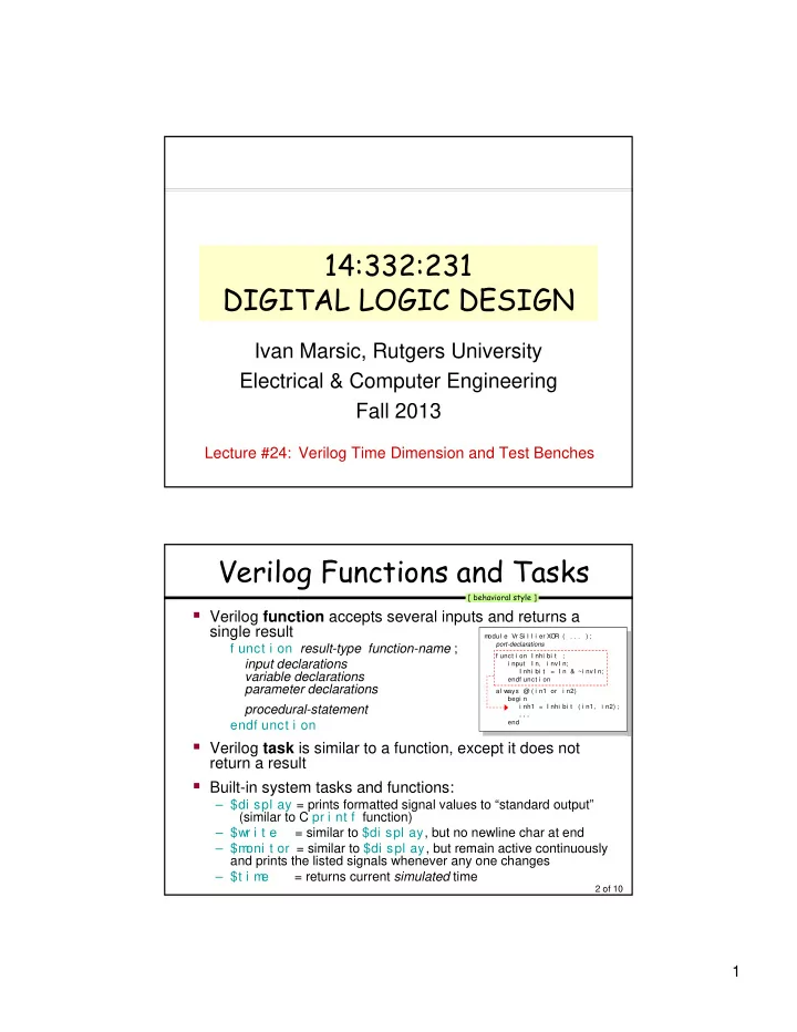
Verilog Functions and Tasks
- Verilog function accepts several inputs and returns a
single result
f unct i on result-type function-name ; input declarations variable declarations parameter declarations procedural-statement endf unct i on
- Verilog task is similar to a function, except it does not
return a result
- Built-in system tasks and functions:
– $di spl ay = prints formatted signal values to “standard output” (similar to C pr i nt f function) – $wr i t e = similar to $di spl ay, but no newline char at end – $m
- ni t or = similar to $di spl ay, but remain active continuously
and prints the listed signals whenever any one changes – $t i m e = returns current simulated time
[ behavioral style ]
m
- dul e Vr Si l l i er XO
R ( . . . ) ; port-declarations f unct i on I nhi bi t ; i nput I n, i nvI n; I nhi bi t = I n & ~i nvI n; endf unct i on al ways @ ( i n1 or i n2) begi n i nh1 = I nhi bi t ( i n1, i n2) ; . . . . . . end m
- dul e Vr Si l l i er XO
R ( . . . ) ; port-declarations f unct i on I nhi bi t ; i nput I n, i nvI n; I nhi bi t = I n & ~i nvI n; endf unct i on al ways @ ( i n1 or i n2) begi n i nh1 = I nhi bi t ( i n1, i n2) ; . . . . . . end